Supercharge Your Innovation With Domain-Expert AI Agents!

How to set power coupler, terminal and coupling parameters

A technology of power coupler and coupling parameters, which is applied in the direction of sub-office equipment, telephone structure, electrical components, etc., can solve the problems of power parameter mismatch, affecting antenna radiation power, etc., and achieve the effect of eliminating the reduction of antenna radiation power

Active Publication Date: 2021-01-08
VIVO MOBILE COMM CO LTD
View PDF4 Cites 0 Cited by
  • Summary
  • Abstract
  • Description
  • Claims
  • Application Information

AI Technical Summary

Problems solved by technology

[0004] The embodiment of the present invention provides a power coupler, a terminal, and a method for setting coupling parameters, so as to solve the problem in the prior art that the power parameters obtained in the early stage debugging do not match the power parameters required for actual use and affect the radiation power of the antenna

Method used


Image

  • How to set power coupler, terminal and coupling parameters
  • How to set power coupler, terminal and coupling parameters
  • How to set power coupler, terminal and coupling parameters

Examples


Embodiment 1

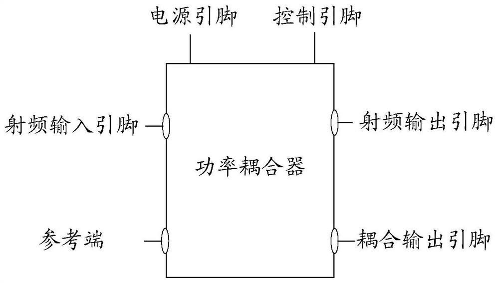
[0025] refer to figure 1 , shows a schematic structural diagram of a power coupler provided by an embodiment of the present invention. The power coupler is provided with a control pin, a radio frequency input pin, a radio frequency output pin, a reference terminal and a coupled output pin;

[0026] The control pin is used to receive a control signal corresponding to the application scenario;

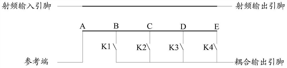
[0027] A radiation power path is formed between the radio frequency input pin and the radio frequency output pin; the radiation power path is used to transmit the radiation power of the antenna;

[0028] A coupling path is formed between the reference terminal and the coupling output pin; the coupling path is used to set a coupling parameter coupled with the radiation power path according to the control signal.

[0029] In this embodiment, the power coupler has a control pin, a radio frequency input pin, a radio frequency output pin, a reference terminal and a coupling output pin, the ...

Embodiment 2

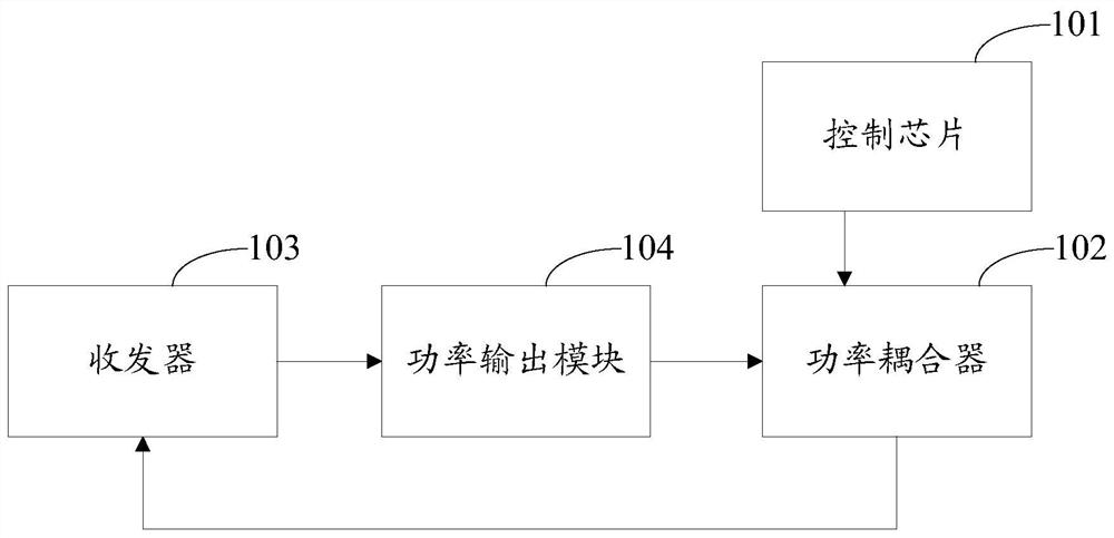
[0039] refer to image 3 , shows a schematic structural diagram of a terminal provided by an embodiment of the present invention. The terminal includes a control chip 101 and a power coupler 102 as described in Embodiment 1;

[0040] The control chip 101 is connected to the power coupler 102;

[0041] The control chip 101 is configured to determine an application scenario of the terminal, and send a control signal to the power coupler 102 according to the application scenario;

[0042] The power coupler 102 is configured to set coupling parameters according to the control signal.

[0043] In this embodiment, the control chip 101 is connected to a control pin of the power coupler 102 to input a control signal to the power coupler 102 . Specifically, the control chip 101 determines an application scenario of the terminal, and sends a control signal to the power coupler 102 according to the application scenario. For example, the control chip 101 determines that the terminal i...

Embodiment 3

[0060] refer to Figure 5 , shows a flowchart of steps of a method for setting a coupling parameter provided by an embodiment of the present invention. Applied to the terminal described in Embodiment 2, the method includes:

[0061] Step 201, determining an application scenario of the terminal.

[0062] In this embodiment, the terminal can be equipped with an infrared sensor, a geomagnetic sensor, etc., and judge the application scenario of the terminal according to the data collected by the sensor. Optionally, the application scene includes at least one of a free placement scene, a hand-held scene, and a call scene. For example, according to the infrared data collected by the infrared sensor, it can be judged that the terminal is in a free placement scene, it can also be judged that the terminal is in a hand-holding scene such as one-handed holding or two-handed holding, and it can also be judged that the terminal is in a call where both hands and heads are in contact with ...


PUM


Abstract

The invention provides a power coupler, a terminal and a setting method for coupling parameters. The power coupler is provided with a control pin, a radio-frequency input pin, a radio-frequency outputpin, a reference end and a coupling output pin, wherein the control pin is used for receiving a control signal corresponding to an application scene; a radiant power path is formed between the radio-frequency input pin and the radio-frequency output pin; the radiant path is used for transmitting radiant power of an antenna; a coupling path is formed between the reference end and the coupling output pin; and the coupling path is used for setting the coupling parameters for coupling with the radiant power path according to the control signal. Through the embodiment of the invention, the problemof lowering of antenna radiant power due to the fact that the coupling parameters are mismatched with the application scene can be improved or eliminated.

Description

technical field [0001] The invention relates to the technical field of mobile terminals, in particular to a power coupler, a terminal and a method for setting coupling parameters. Background technique [0002] As users pursue the ultimate appearance of mobile terminals, models such as "full screen" and "all metal" are launched. These designs leave less and less space for antennas, and antennas must meet basic communication needs. Therefore, the radiation power of the antenna has gradually become a bottleneck in the development of mobile terminals. [0003] At present, the control of radiation power is mainly realized by power coupler. However, due to the load of the signal transmission path in actual use, there is often a certain deviation from the load added in the previous debugging, and the traditional power coupler has fixed coupling parameters, which cannot correct this deviation. Therefore, the power parameters obtained in the early stage debugging will not match the...

Claims


Application Information

Patent Timeline
Patent Type & Authority Patents(China)
IPC IPC(8): H04B1/3827H04B1/40H04M1/02
CPCH04B1/3833H04B1/40H04M1/026
Inventor 胡亮
Owner VIVO MOBILE COMM CO LTD
Features
  • R&D
  • Intellectual Property
  • Life Sciences
  • Materials
  • Tech Scout
  • Unparalleled Data Quality
  • Higher Quality Content
  • 60% Fewer Hallucinations
Learn More