Systems and methods for modeling, analyzing, detecting, and monitoring fluid networks
A fluid network, fluid technology, applied in the field of monitoring and detection of fluid networks, modeling, and analysis, to solve problems such as infrastructure, water quality, or health that are not found and resolved
- Summary
- Abstract
- Description
- Claims
- Application Information
AI Technical Summary
Problems solved by technology
Method used
Image

Examples
Embodiment approach 1
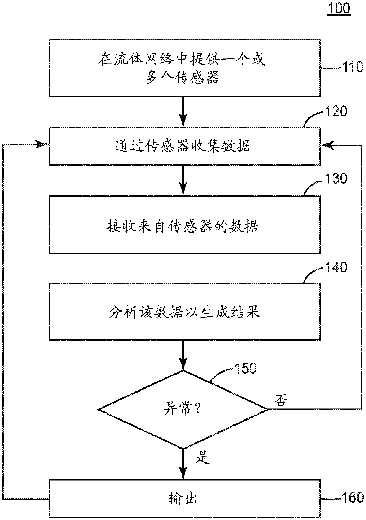
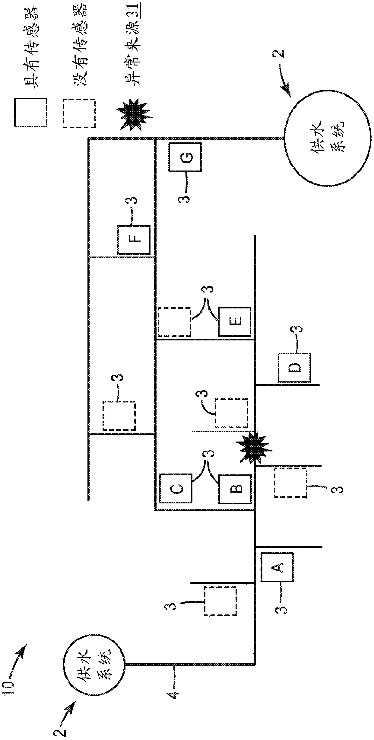
[0098] Embodiment 1 is a method of optimally determining sensor or infrastructure placement in a fluid network comprising:
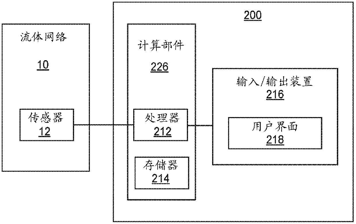
[0099] Create a model of the fluid network, wherein the model includes i) a plurality of directional connection nodes representing fluid infrastructure disposed in the fluid network and ii) a node positioned at one or more selected locations in the fluid network or multiple sensors;
[0100] representing the model as a matrix data structure associated with processors disposed outside the fluid network;
[0101] analyzing the matrix by the processor to assess whether each node of the model satisfies one or more locateability criteria, wherein analyzing the matrix includes interpreting and executing instructions associated with the processor; and
[0102] The sensor or infrastructure placement in the fluid network is determined based on the results of analyzing the matrix.
[0103] Embodiment 2 is the method of embodiment 1, wherein the model comprises o...
PUM
 Abstract
Description
Claims
Application Information