Surge protection method for turbocharging system compressor air distribution control and surge protection device for realizing same
A technology of turbocharging system and air volume control, which is applied to components of pumping devices for elastic fluids, pump control, mechanical equipment, etc., and can solve the problems of inability to quickly respond to air volume requirements, reduced boiler performance, and conservative safety margins, etc. problem, to achieve the effect of performance improvement, performance improvement, and accelerated response
- Summary
- Abstract
- Description
- Claims
- Application Information
AI Technical Summary
Problems solved by technology
Method used
Image


Examples
specific Embodiment approach 1
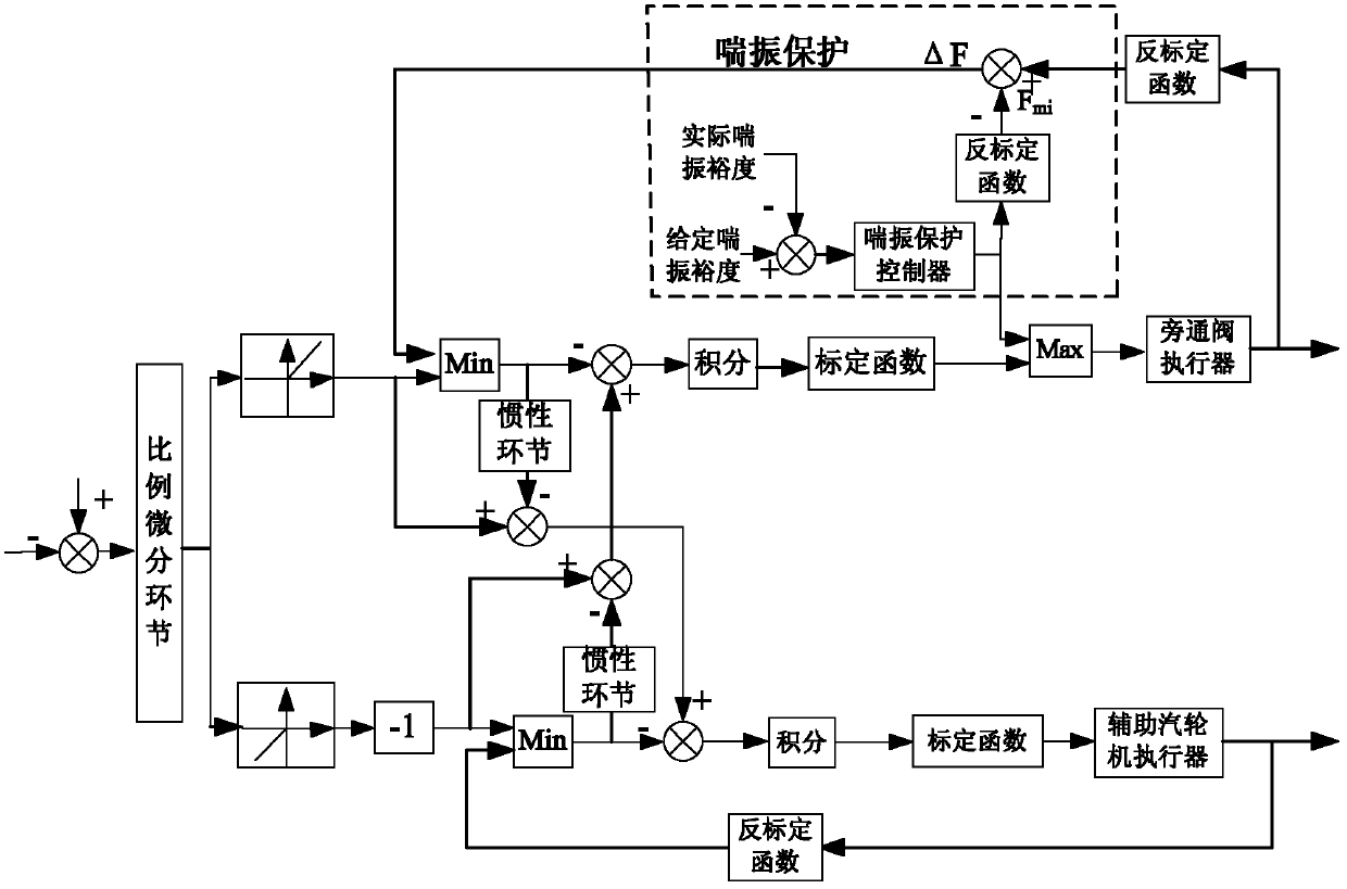
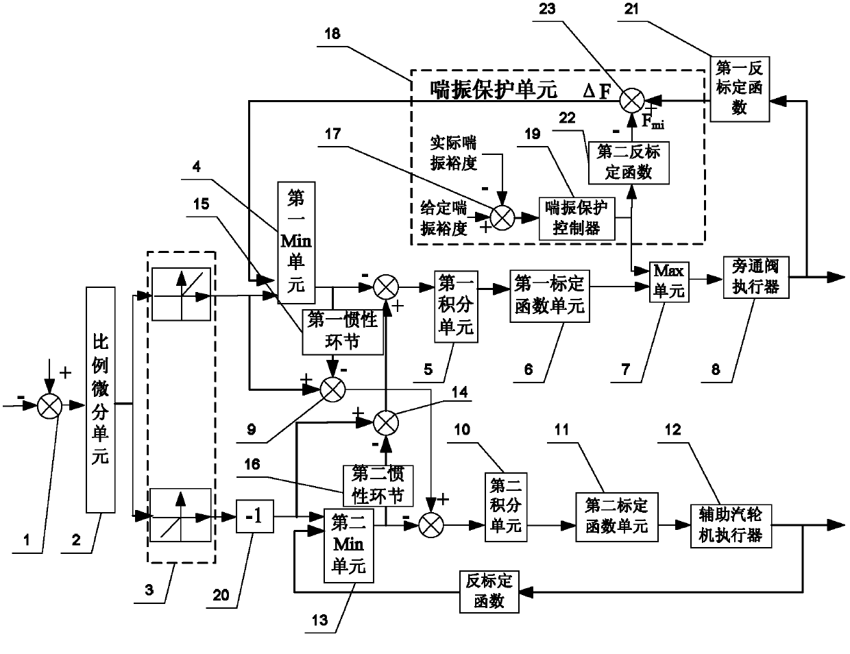
[0025] Specific implementation mode one: the following combination figure 1 To illustrate this embodiment, the surge protection method described in this embodiment is adjusted on the basis of the ventilation rate allowed by the inherent safety margin of the turbocharger system compressor, and it includes the following steps:
[0026] Step 1: Make a difference between the set air volume given signal of the compressor and the actual signal of the air volume of the compressor acquired in real time, and then adjust through the proportional differential unit to generate the air volume control signal;
[0027]Step 2: Process the air volume control signal through the cross-limiting unit, output the air volume signal to be adjusted, and select the corresponding air volume distribution method according to the air volume signal to be adjusted, and then adjust the air volume of the compressor according to the selected air volume distribution method .
specific Embodiment approach 2
[0028] Specific implementation mode two: the following combination figure 1 Describe this embodiment. This embodiment is a further description of Embodiment 1. In the second step, the corresponding air volume distribution method is selected according to the air volume signal to be adjusted, and then the air volume of the compressor is adjusted according to the selected air volume distribution method. The specific method is:
[0029] When the air volume control signal is greater than 0, the air volume signal to be adjusted is used as the air volume signal to be increased by the compressor, and the following two steps are performed at the same time:
[0030] Step 2A: Compare the air volume signal to be increased by the compressor with the allowable ventilation volume decrement signal of the current bypass valve, and use the signal with a smaller value as the air volume decrement signal of the bypass valve, and the air volume decrement signal of the bypass valve The quantity sig...
specific Embodiment approach 3
[0035] Specific implementation mode three: the following combination figure 1 Describe this embodiment. This embodiment is a further description of Embodiment 2. In the step 2B, the air volume signal to be increased by the compressor is different from the air volume decrement signal of the bypass valve. The air volume decrement signal is the air volume decrement signal after the action of the inertia link.
[0036] The addition of the inertia link described in this embodiment can ensure that the incremental command signal of the auxiliary steam turbine is increased while the bypass valve is preferentially operated, so that the valve of the auxiliary steam turbine is opened larger, which helps to accelerate the air volume response.
PUM
 Abstract
Description
Claims
Application Information