
Lifebuoy waste recycling device
A waste recycling and lifebuoy technology, which is applied in the fields of removing smoke and dust, cleaning methods and utensils, and grain processing, etc., can solve the problems of easy explosion, material waste, danger, etc., and achieves the effect of high collection efficiency, convenient use and reasonable structure.
- Summary
- Abstract
- Description
- Claims
- Application Information
AI Technical Summary
Problems solved by technology
Method used
Image

Examples
Embodiment Construction
[0016] The following will clearly and completely describe the technical solutions in the embodiments of the present invention with reference to the accompanying drawings in the embodiments of the present invention. Obviously, the described embodiments are only some, not all, embodiments of the present invention.
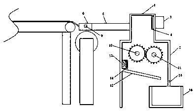
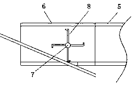
[0017] refer to Figure 1-2 , a lifebuoy waste recovery device, including a collection box 1 and a crushing box 2, the collection box 1 is located at the top of the crushing box 2, and the collection box 1 is connected to the crushing box 2, and a negative pressure device is installed on the outer wall of the collection box 1 Fan 3, the first barrier net cover 4 is fixedly installed on the inner wall of the collection box 1 near the side of the negative pressure fan 3, and the collection pipe 5 is installed on the side of the collection box 1 away from the negative pressure fan 3, and one end of the collection pipe is fixedly installed with The collector 6, the colle...
PUM
 Abstract
Description
Claims
Application Information