Method and apparatus for monitoring belt tension of a drive belt of a ring spinning machine

A technology of ring spinning machine and transmission belt, which is applied in the direction of spinning machine, continuous winding spinning machine, textile and paper making, etc., and can solve problems such as complex cost

Active Publication Date: 2022-07-12
SAURER SPINNING SOLUTIONS GMBH & CO KG
View PDF8 Cites 0 Cited by
  • Summary
  • Abstract
  • Description
  • Claims
  • Application Information

AI Technical Summary

Problems solved by technology

[0016] The methods and devices described above have thoroughly proven themselves in practice, but in some cases are very complex and costly

Method used


Image

  • Method and apparatus for monitoring belt tension of a drive belt of a ring spinning machine
  • Method and apparatus for monitoring belt tension of a drive belt of a ring spinning machine
  • Method and apparatus for monitoring belt tension of a drive belt of a ring spinning machine

Examples


Embodiment Construction

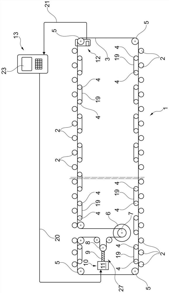
[0038] figure 1 A highly schematic top view of a ring spinning machine 1 is shown, the spindles of which are frictionally driven by an endless tangential belt. The ring spinning machine 1 has a plurality of tables on both machine longitudinal sides, which tables are each equipped with such spindles 2 . As known and therefore not described in more detail, so-called ring spinning bobbins are produced on said spindle 2; said ring spinning bobbins have relatively little yarn material and are thus rewound onto so-called automatic winders to form cross-wound packages in a subsequent production step.

[0039] The spindles 2 of the ring spinning machine 1 are mounted freely and rotatably and are frictionally driven by an endless tangential belt 3 acting on the drive disc of each spindle 2 . In order to ensure a specific contact pressure of the tangential belt 3 against the drive discs of the spindles 2, so-called pressure rollers 4 are usually additionally provided between the spind...


PUM


Abstract

Method and apparatus for operating a ring spinning machine. The present invention relates to a method and apparatus for monitoring the belt tension of a drive belt of a ring spinning machine with multiple thread positions, the spindles of which are frictionally driven by an endless tangential belt during spinning operations. According to the invention, monitoring of the belt tension of the tangential belt by means of a sensor device is provided, which sensor device is connected to a machine control system of a ring spinning machine, wherein the belt tension data determined by means of the sensor device are evaluated in the machine control system. Processed and visualized with the aid of a display.

Description

technical field [0001] The present invention relates to a method and apparatus for monitoring the belt tension of a drive belt of a ring spinning machine with multiple yarn positions, the spindles of which are frictionally driven by an endless tangential belt during spinning operations. Background technique [0002] Spinning machines with multiple thread positions, the spindles of which are frictionally driven by an endless tangential belt, have been known in the textile industry for a long time. [0003] Such multi-position spinning machines (eg, ring spinning machines) typically have a number of identical tables arranged adjacent to each other on both sides of the machine longitudinal axis and whose working elements are separated by lengths of the machine length. Circulating annular traction elements are combined to drive. [0004] In the case of a ring spinning machine, the individual stations are each equipped with, for example, freely rotatably mounted spindles, and a ...

Claims


Application Information

Patent Timeline
Patent Type & Authority Patents(China)
IPC IPC(8): D01H13/14D01H13/26D01H1/241D01H1/20D01H1/02
CPCD01H1/02D01H1/20D01H1/241D01H13/14D01H13/26
Inventor G·赫伯特
Owner SAURER SPINNING SOLUTIONS GMBH & CO KG
Why Eureka
Try Eureka