
Laser-cladding nozzle

A technology of laser cladding and nozzle, which is applied in the direction of spraying device, liquid spraying device, metal material coating process, etc., and can solve the problems of not using actual production application, powder colliding with each other, complex nozzle design, etc.

Active Publication Date: 2015-05-13
WENZHOU UNIVERSITY
View PDF4 Cites 21 Cited by
  • Summary
  • Abstract
  • Description
  • Claims
  • Application Information

AI Technical Summary

Problems solved by technology

However, the powder flow is fed at an angle after all, and the powders collide with each other when they converge at the converging point. At the same time, there will be turbulent airflow in the shielding gas to disturb the converging of the powder. Various factors make the effect of the powder in the actual converging process unsatisfactory.
and most nozzle designs are too complex to take advantage of practical production applications

Method used


Image

  • Laser-cladding nozzle
  • Laser-cladding nozzle
  • Laser-cladding nozzle

Examples


Embodiment Construction

[0021] The specific implementation manners of the present invention will be further described in detail below in conjunction with the accompanying drawings and embodiments. The following examples are used to illustrate the present invention, but are not intended to limit the scope of the present invention.

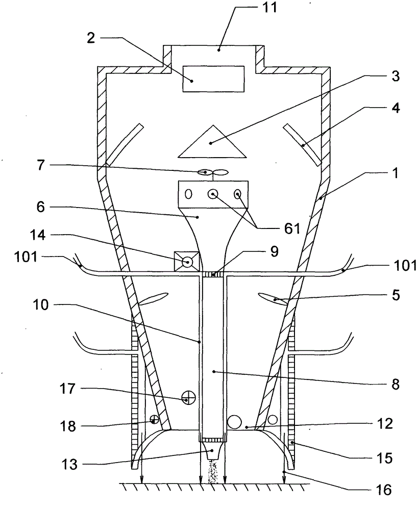
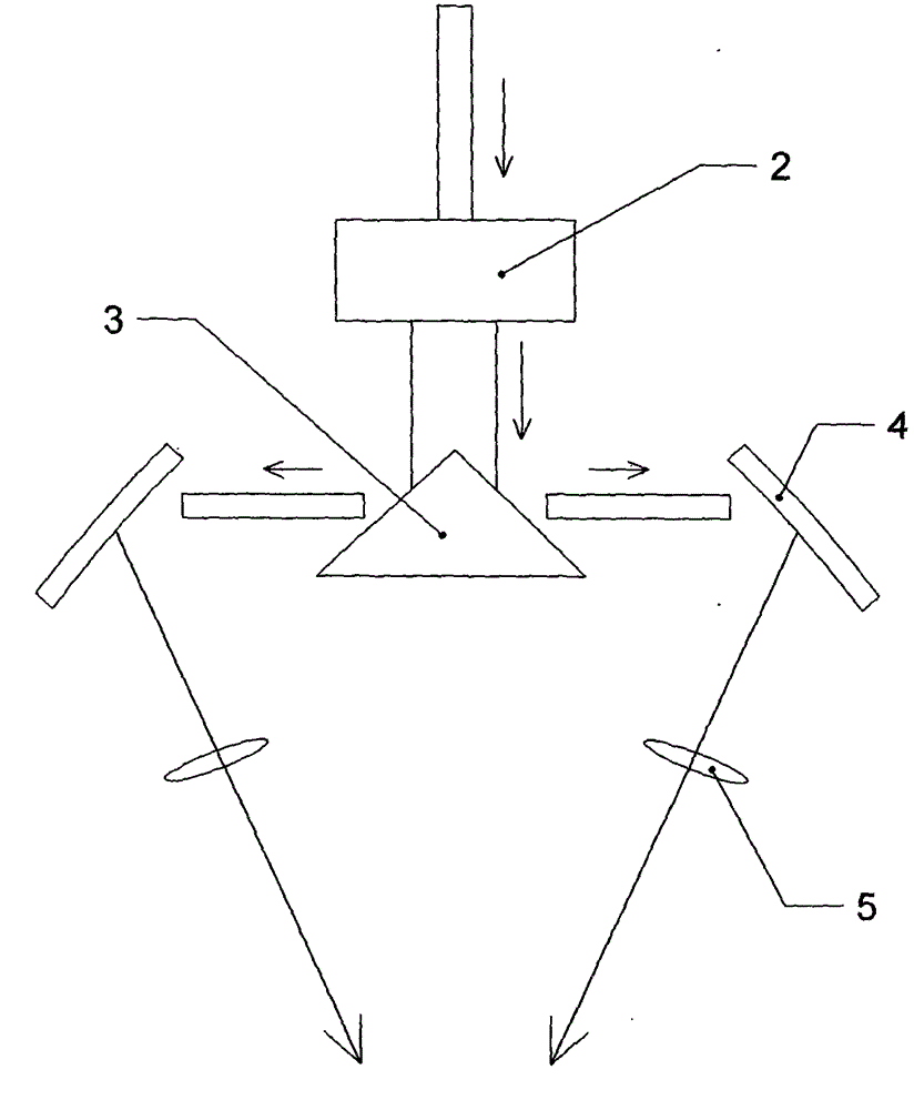
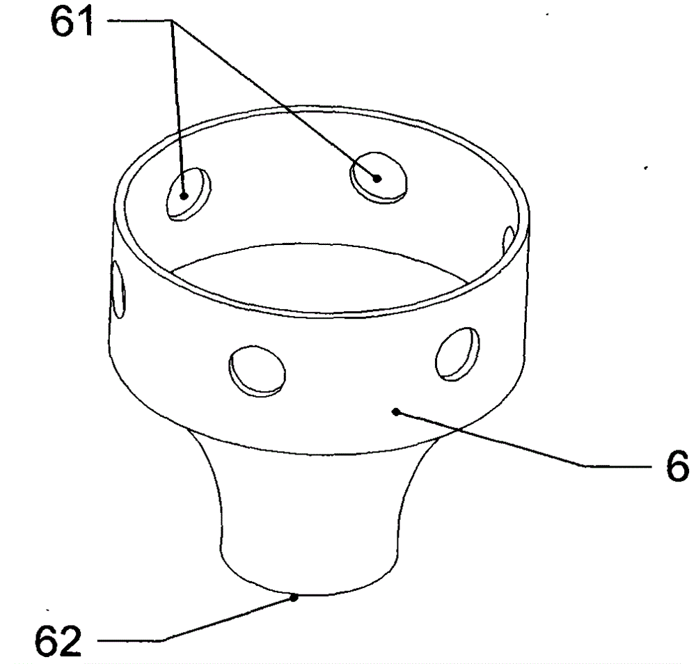
[0022] like figure 2 As shown, a laser cladding nozzle includes a cylinder body 1, the upper end and the lower end of the cylinder body 1 are respectively provided with a light inlet 11 and a light outlet 12, and the inside of the cylinder 1 and near the light inlet 11 are from top to bottom A beam expander 2 and a beam splitter 3 are arranged in turn. The longitudinal section of the beam splitter 3 is triangular and the mirror surface faces the light inlet 11. Reflectors 4 are respectively arranged on the inner wall of the cylinder body 1 on both sides of the beam splitter 3. The two The mirror surfaces of the reflective mirror 4 are respectively opposite to the two mir...


PUM


Abstract

The invention relates to a laser-cladding nozzle, and belongs to the technical field of laser processing. The nozzle is characterized in that a beam of laser is turned into two beams of laser through an effect of a beam splitter and the two beams of laser enter a molten pool from laser channels on the two sides of the nozzle; powder is fed into a powder chamber from multiple directions and do downward motion under the effect of a minitype air blower so that a uniform powder stream is formed under the effect of a powder separation sieve; the convergence accuracy of the periphery of the powder is guaranteed by a circle of collimation protecting gas; because an angle sensor arranged in the middle of the nozzle, the protection gas quantity can be increased when the nozzle inclines, the segregation, caused by gravity, of the powder is possibly reduced, annular protecting gas also exists at the periphery of the front end of the nozzle and can protect the molten pool in a coverage manner; a middle nozzle can cool the nozzle by using a spiral cooling water channel; due to a protective cover of the end part, full reflection of the laser is facilitated and work returning pieces and powder can be fully utilized; a cooling water path for cooling in time is also arranged on the protective cover. The laser-cladding nozzle has a simple structure and is high in powder convergence accuracy; moreover, the light-powder coupling accuracy is improved, and the collimation property and the utilization rate of the powder can be improved.

Description

technical field [0001] The invention relates to the field of laser processing, in particular to a laser cladding nozzle. Background technique [0002] Laser cladding technology emerged in the 1980s and is an advanced surface strengthening, modification and repair technology for metal parts. Specifically, it refers to placing the selected coating material on the surface of the coated substrate with different filler methods, melting it and a thin layer of the substrate surface at the same time through laser irradiation, and forming a very low dilution after rapid solidification and blending with the substrate material. Forming a metallurgically bonded surface coating, thereby significantly improving the wear resistance, corrosion resistance, heat resistance, and oxidation resistance of the base material surface. [0003] The most commonly used powder feeding method for laser cladding technology is synchronous powder feeding. These include the side-axis powder feeding method ...

Claims


Application Information

Patent Timeline
Patent Type & Authority Applications(China)
IPC IPC(8): C23C24/10
CPCB05B7/16C23C24/10
Inventor 陈希章袁其兵薛伟
Owner WENZHOU UNIVERSITY
Learn More