
Backstitching mechanism below sewing machine

A sewing machine and reverse sewing technology, which is applied in the direction of sewing machine components, cloth feeding mechanism, sewing equipment, etc., can solve the problems of unsmooth operation, high manufacturing cost, and inability to invert large or thick work objects, etc.

Pending Publication Date: 2019-04-23
ANHUI JIEYU SHOEMAKING MACHINERY TECH CO LTD
View PDF0 Cites 1 Cited by
  • Summary
  • Abstract
  • Description
  • Claims
  • Application Information

AI Technical Summary

Problems solved by technology

[0002] Generally, it is necessary to reverse the sewing machine during operation. For small workpieces, you only need to turn the workpiece upside down, but large or thick workpieces cannot be reversed.
Commonly used industrial sewing machines are equipped with a reverse sewing device. The reverse sewing device uses a series of conversion gear devices to change the conveying and related systems to perform reverse sewing. This type of device is also available, but the structure is complicated and the manufacturing cost is high. , at the same time, the gear change system is prone to failure and the operation is not smooth

Method used


Image

  • Backstitching mechanism below sewing machine
  • Backstitching mechanism below sewing machine
  • Backstitching mechanism below sewing machine

Examples


Embodiment Construction

[0045] In order to make the purpose, technical solutions and advantages of the embodiments of the present invention clearer, the technical solutions in the embodiments of the present invention will be clearly and completely described below in conjunction with the embodiments of the present invention. Obviously, the described embodiments are part of the present invention Examples, not all examples. Based on the embodiments of the present invention, all other embodiments obtained by persons of ordinary skill in the art without creative efforts fall within the protection scope of the present invention.

[0046] In the description of the present invention, it should be noted that the orientation or positional relationship indicated by the terms "vertical", "upper", "lower" and "horizontal" are based on the orientation or positional relationship shown in the drawings, and are only for It is convenient to describe the present invention and simplify the description, but does not indi...


PUM


Abstract

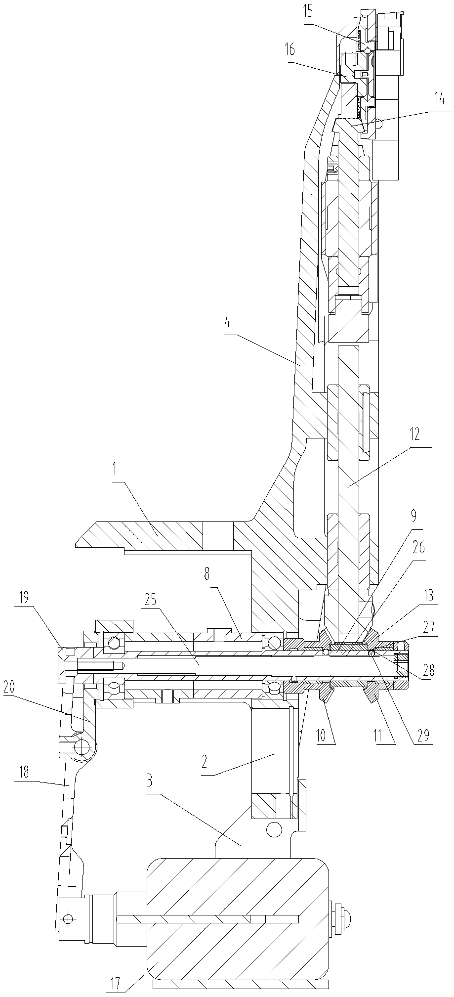
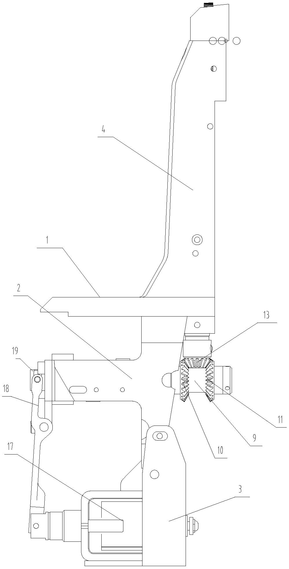
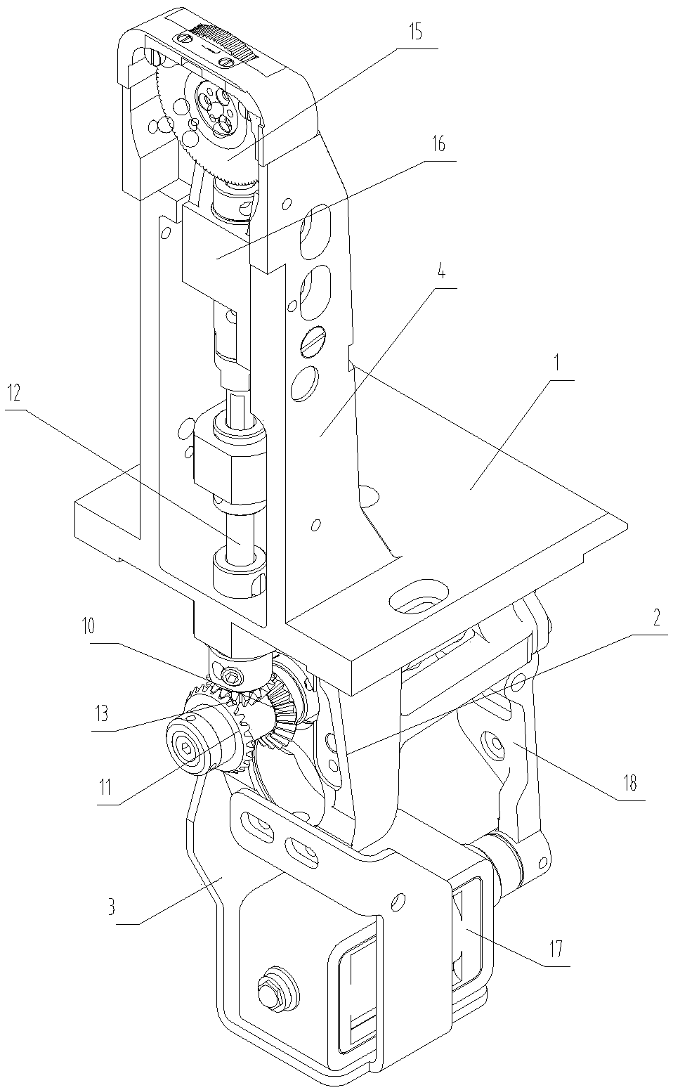
The invention discloses a backstitching mechanism below a sewing machine. A driving shaft performs forward and backward motion to drive a clamping piece to swing; a pulling rod on the clamping piece pulls a one-way bearing to perform one-way rotation so as to drive a first driven shaft to rotate; the teeth on the first driven shaft drive a gear to rotate; the gear drives a second driven shaft to rotate; a feeding mechanism is arranged at the upper end of the second driven shaft; in this case, the feeding mechanism feeds forwards; a backstitching electromagnet is opened; the lower end of an overturning plate is pulled and overturned by the backstitching electromagnet; the overturning plate overturns around a point which is hinged to a vertical plate; the upper end of the overturning plate pulls an inner shaft; the position of an annular groove of the inner shaft moves therewith, so that the positions of two steel balls in the inner shaft and the annular groove are changed; the steel ball which is positioned out of the annular groove falls into the annular groove, and the steel ball which is positioned in the annular groove rises out of the annular groove to complete the alternationof a first bevel gear and a second bevel gear; and the second driven shaft rotates backwards so as to drive the feeding mechanism to rotate backwards to complete backstitch. Therefore, the situation of tooth breaking is avoided.

Description

Technical field: [0001] The invention relates to the technical field of sewing machines, in particular to a bottom reverse sewing mechanism of a sewing machine. Background technique: [0002] Generally, sewing machines need reverse sewing during operation. For small work items, it is only necessary to turn them upside down, but large or thick work items cannot be turned upside down. Commonly used industrial sewing machines are equipped with a reverse sewing device. The reverse sewing device uses a series of conversion gear devices to change the conveying and related systems to perform reverse sewing. This type of device is also available, but the structure is complicated and the manufacturing cost is high. , At the same time, the gear change system is prone to failure and the operation is not smooth. Invention content: [0003] The purpose of the present invention is to provide a sewing machine bottom reverse sewing mechanism. [0004] Technical problem to be solved by t...

Claims


Application Information

Patent Timeline
Patent Type & Authority Applications(China)
IPC IPC(8): D05B27/10
CPCD05B27/10
Inventor 张应旗曹登科
Owner ANHUI JIEYU SHOEMAKING MACHINERY TECH CO LTD
Learn More