Section steel column and construction method thereof

A technology of section steel and locking steel wire, applied in the direction of columns, piers, pillars, etc., can solve the problems of reducing the bearing capacity of section steel columns, affecting the bearing capacity of section steel, etc., to achieve convenient processing and construction, maintaining integrity, and convenient construction. Effect

Inactive Publication Date: 2019-04-23
广州市天作建筑规划设计有限公司
View PDF7 Cites 0 Cited by
  • Summary
  • Abstract
  • Description
  • Claims
  • Application Information

AI Technical Summary

Problems solved by technology

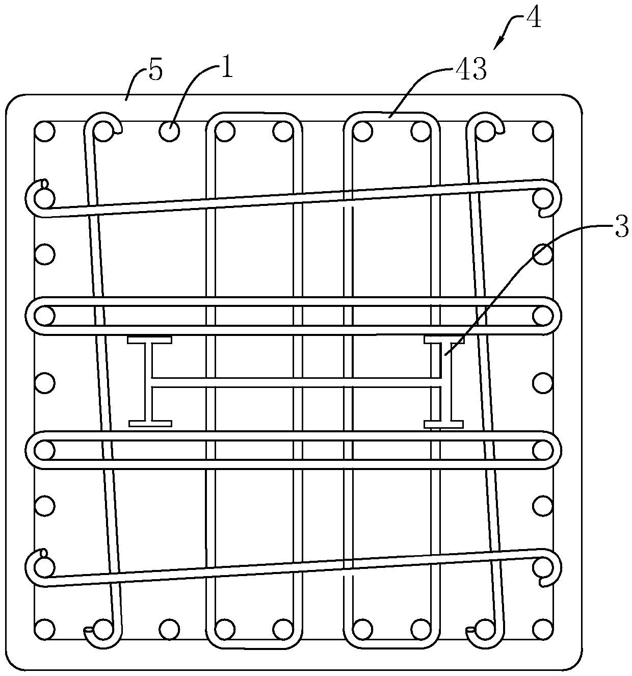
[0004] The disadvantages of the above-mentioned prior art are that punching holes on the profiled steel will affect the load-bearing capacity of the profiled steel, resulting in a reduction in the load-bearing capacity of the profiled steel column

Method used


Image

  • Section steel column and construction method thereof
  • Section steel column and construction method thereof
  • Section steel column and construction method thereof

Examples


Embodiment 1

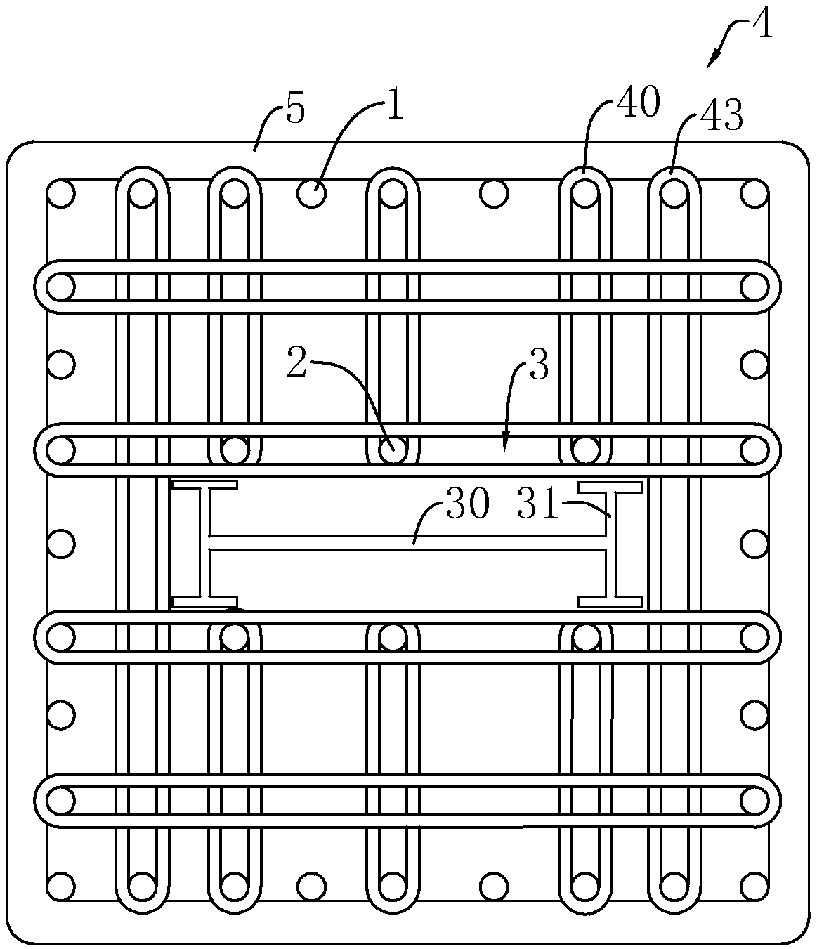
[0039] Embodiment 1, with reference to figure 2 , a shaped steel column includes shaped steel 3 , reinforcing longitudinal bars 1 , structural longitudinal bars 2 and connecting bars 4 .

[0040] refer to figure 2 , in the present embodiment, the shaped steel 3 is set and fixed at the center of the shaped steel column, the structural longitudinal bars 2 are fixed on both sides of the shaped steel 3, and there are vertically arranged reinforcing longitudinal bars 1 evenly distributed around the shaped steel 3, and the shaped steel 3 and the reinforced longitudinal bars 1 A connecting bar 4 is connected between the reinforcing longitudinal bars 1 facing inwardly in the gap. The connecting bar 4 includes a long stirrup 43 and a short stirrup 40. A long stirrup 43 is selected between two opposite reinforcing longitudinal bars 1. 43 has a fixing function between the reinforcing longitudinal bars 1, and increases the strength of the shaped steel column at the same time.

[0041]...

Embodiment 2

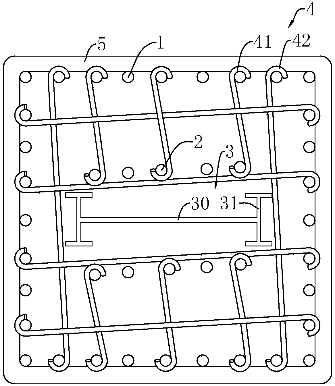
[0044] Embodiment 2, the difference between this embodiment and embodiment 1 is: refer to image 3 , the connecting rib 4 between two opposite reinforcing longitudinal bars 1 is a long tie bar 42, and the connecting bar 4 connected between the structural longitudinal bar 2 and the reinforcing longitudinal bar 1 is an end tie bar.

[0045] A construction method of a shaped steel column, comprising the following steps: A construction method of a shaped steel column, characterized in that: comprising the following steps:

[0046] S1: Stand the section steel 3 vertically at the preset position, as follows:

[0047] Stand the section steel 3 in the column foundation and fix it with concrete.

[0048] S2: Stand the structural longitudinal reinforcement 2 on the outside of the section steel 3, as follows:

[0049] Paste the structural longitudinal reinforcement 2 on both sides of the section steel 3 and fix it in the column foundation.

[0050] S3: Stand the reinforcing longitudin...


PUM


Abstract

The invention discloses a section steel column and a construction method thereof and relates to the technical field of building structures. According to the technical solution, the section steel column is characterized in that the section steel column comprises section steel cast by concrete, longitudinal reinforcing ribs located around the section steel, and structural longitudinal ribs close tothe periphery of the section steel and located between the section steel and the longitudinal reinforcing ribs, and connecting ribs are fixedly connected between the structural longitudinal ribs and the longitudinal reinforcing ribs arranged opposite to the structural longitudinal ribs. By means of the section steel column, the technical problem that holes need to be punched in the section steel for allowing stirrups to pass through when the stirrups are connected, and consequently the strength of the section steel is affected can be solved and the section steel column has the advantage of increasing the strength of the section steel.

Description

technical field [0001] The invention relates to the technical field of building structures, in particular to a shaped steel column and a construction method thereof. Background technique [0002] Sectional steel column is a column made of reinforced concrete and section steel. It is the most basic load-bearing component in various engineering structures such as houses, bridges, and hydraulic engineering. In the actual construction process, steel columns need to be spliced ​​with reinforced concrete. [0003] refer to figure 1 , the existing shaped steel column includes, reinforced longitudinal reinforcement 1, and shaped steel 3 positioned at the center of the shaped steel column, the periphery of the longitudinal reinforcement is covered with locking stirrups 5, and connecting ribs 4 are connected between the two opposite longitudinal reinforcements. Among them, the connecting bar 4 is a stirrup. Since the shaped steel column has a shaped steel 3, when connecting the stir...

Claims


Application Information

Patent Timeline
Patent Type & Authority Applications(China)
IPC IPC(8): E04C3/32E04G21/00
CPCE04C3/32E04G21/00
Inventor 金雪峰
Owner 广州市天作建筑规划设计有限公司
Why Eureka
Try Eureka