Paving device for floor tiles

A technology for laying devices and floor tiles, which is applied in the direction of construction and building construction, can solve the problems of large labor consumption, low laying efficiency, and low degree of automation, and achieve the effects of increasing automation, improving laying efficiency, and saving manpower and material resources

Active Publication Date: 2019-04-23
ZHENGZHOU NO 1 CONSTR ENG GRP
View PDF7 Cites 26 Cited by
  • Summary
  • Abstract
  • Description
  • Claims
  • Application Information

AI Technical Summary

Problems solved by technology

For example, in large public buildings such as hospitals, municipal buildings, etc., due to the large area of ​​the floor tiles as a whole, the construction process of floor tile laying requires a lot of manpower, material and financial resources, and the laying efficiency is low and the input cost is high.
[0004] At present, most of the commonly used floor tile laying methods are manual laying, which has a low degree of automation and low work efficiency, which is not conducive to accelerating the progress of the project, and requires a lot of labor. Therefore, we urgently need a floor tile laying device to solve the above problems.

Method used


Image

  • Paving device for floor tiles
  • Paving device for floor tiles
  • Paving device for floor tiles

Examples


Embodiment 1

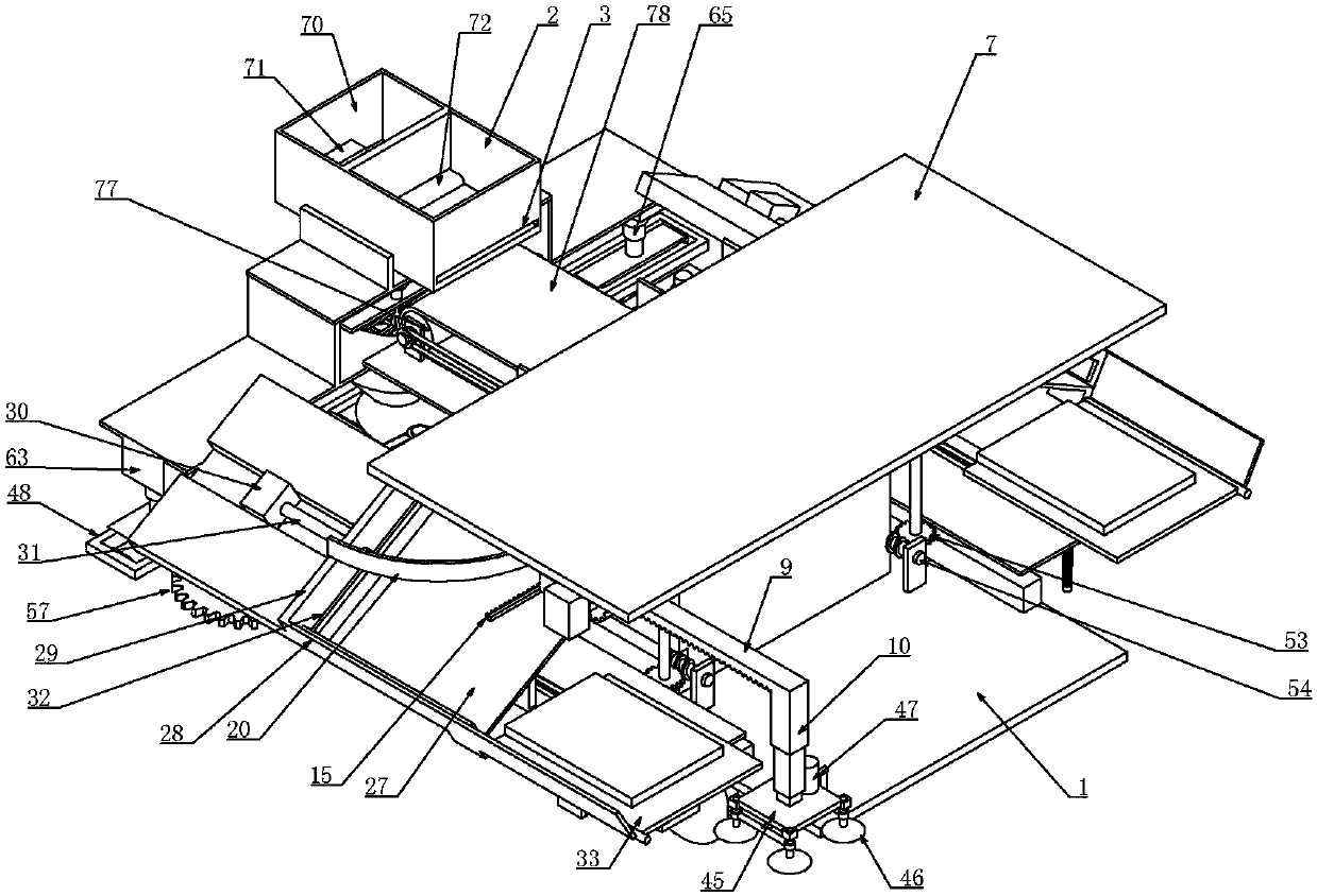
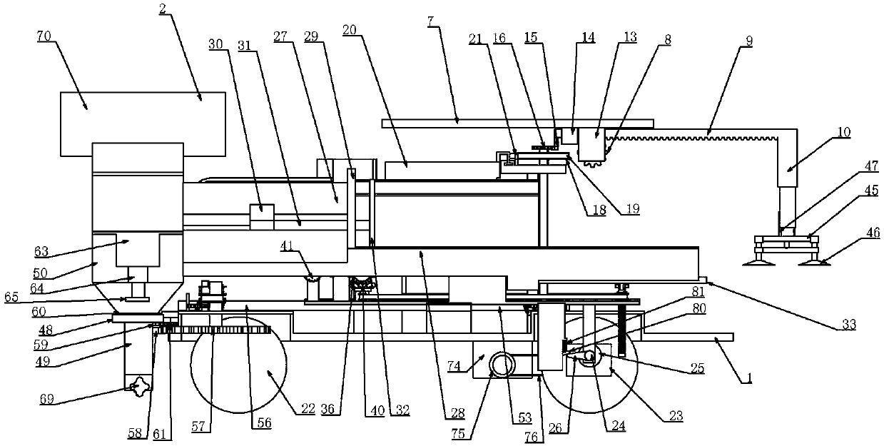
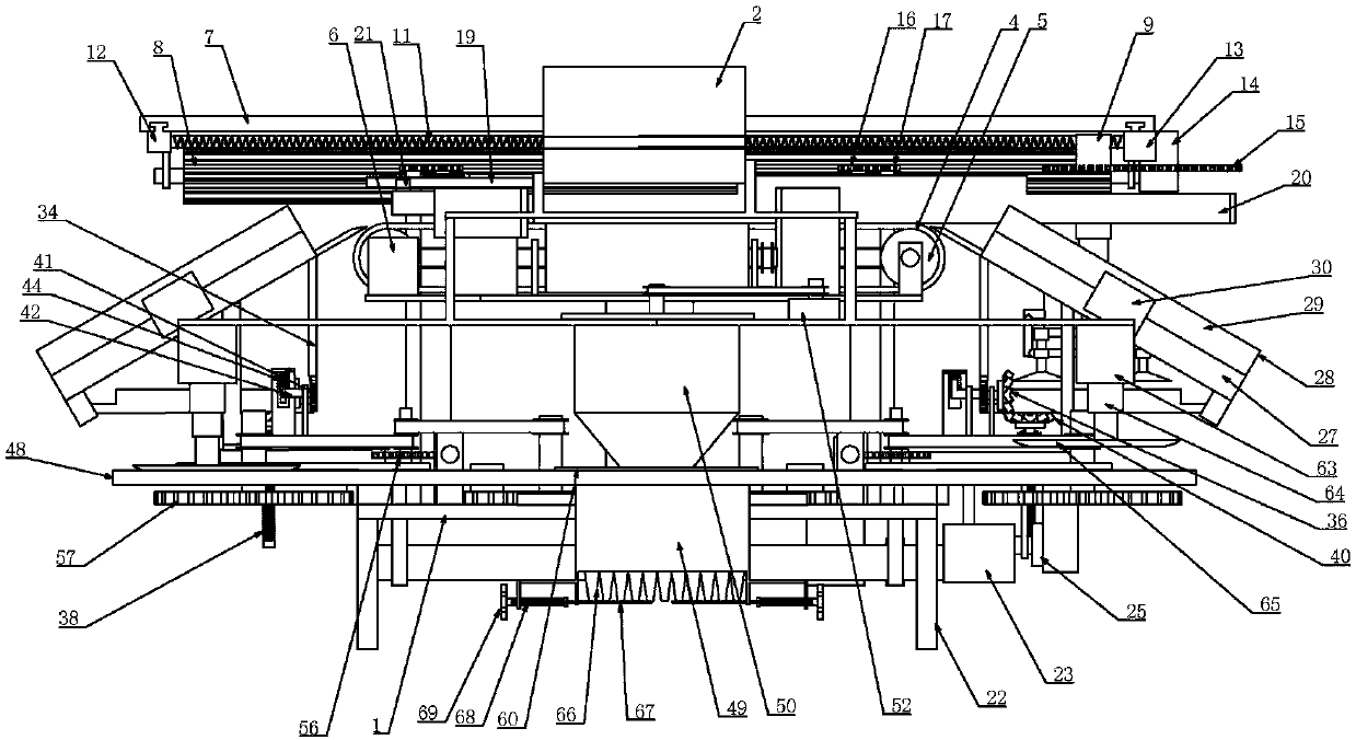
[0040] Example one, combined with Figure 1-17 , A floor tile laying device, comprising a frame 1, characterized in that the upper end of the frame 1 is connected to a brick storage box 2, the upper end of the storage transfer box is open, and the size of the brick storage box 2 matches the size of the tiles to be laid , Or slightly larger than the size of the tiles to be laid, there is a brick outlet 3 at the lower end of the right side of the storage box, and the brick outlet 3 is opened on the right side of the bottom of the storage box. A tile can be produced, the brick outlet 3 is elongated, the brick storage box 2 is connected with a pushing device, and the pushing device can push the floor tiles in the brick storage box 2 from the brick outlet 3, and the pushing device is connected The controller, the controller can trigger the pushing device to complete a stroke, and then push the tiles in the storage box from the brick outlet 3. The pushing device here will be given in...

Embodiment 2

[0044] The second embodiment, on the basis of the first embodiment, combined with the attached Figure 1-17 The tilting device includes an object receiving plate 27 arranged at the exit of the transition belt 4 and placed obliquely. The lower end of the object receiving plate 27 extends out of a barrier 28, and the object receiving plate 27 is formed between the barrier 28 The connecting plate 27 can place the floor tiles on the transition belt 4 on the connecting plate 27. Since the floor tiles are square, when sliding on the connecting plate 27 to the stop bar 28 at the bottom of the connecting plate 27, Self-alignment due to gravity. Of course, the upper end surface of the object plate 27 should be smooth enough. The object plate 27 is connected with a partition rod 29, which is arranged longitudinally along the object plate 27 at its upper end. A hydraulic cylinder 30 placed on the left side of the partition plate is connected to the object plate 27. The hydraulic cylinder ...

Embodiment 3

[0045] The third embodiment, on the basis of the first embodiment, combined with the attached Figure 1-17 The grasping device includes a horizontal plate 45 installed at the lower end of the electric telescopic rod 10, four sets of vacuum suction cups 46 are connected around the horizontal plate 45, and the vacuum suction cup 46 is connected to the upper end of the horizontal plate 45 through a gas pipe. In the vacuum pump 47, the vacuum pump 47 is connected to the control module through the controller. The grasping device here adopts the structure of the vacuum suction cup 46. The structure of the vacuum suction cup 46 has an ideal grasping effect and reliable grasping. The controller and control Module connection, the vacuum pump 47 is controlled by the control module to pump and deflate the working state, so as to complete the grasping and lowering actions.


PUM


Abstract

The invention relates to a paving device for floor tiles. Under a reversing action of a transition belt, floor tiles are conveyed to the front side or rear side of the paving device; the paved floor tiles are not ground during the advancing process of a trolley; a slurry paving device is additionally arranged, so that the two processes of paving slurry and paving floor tiles are respectively arranged in the reciprocating process; during the process of paving floor tiles, a reduction box is connected with an axle end of a wheel and an output shaft of the reduction box is connected with a triggering device through a first driving lever, so that the floor tiles are paved on the paved slurry under a synergistic effect of a first rack, an electric expansion link and a gripping device; due to the existence of reduction box, the intervals of paved floor tiles can be manually adjusted; the paving device is high in practicability; the paving device has a smart structure and is capable of greatly increasing degree of automation of floor tile paving, saving a large quantity of manpower and material resources and greatly increasing paving efficiency of floor tiles.

Description

Technical field [0001] The invention belongs to the technical field of laying devices, and particularly relates to a floor tile laying device. Background technique [0002] Floor tiles are a kind of floor decoration materials, also called floor tiles. Fired with clay. Various specifications. Strong, pressure and wear resistance, and moisture-proof. Some have been glazed for decoration. It is mostly used on the ground and floor of public buildings and civil buildings. There are many types of floor tiles, and there is a lot to choose from. According to the material, they can be divided into glazed tiles, whole-body tiles (anti-slip tiles), polished tiles, [0003] Vitrified tiles, etc. As a large-area floor material, floor tiles use their own colors and textures to create architectural environments with different styles. For example, in large public buildings such as hospitals, municipal buildings and other places, due to the large area of ​​floor tiles, the construction proce...

Claims


Application Information

Patent Timeline
Patent Type & Authority Applications(China)
IPC IPC(8): E04F21/20E04F21/22
CPCE04F21/20E04F21/22
Inventor 张栋梁杨凯杜世涛齐晓娟张峰山原增欢样耀增邱创立蒋丽楠李小艳
Owner ZHENGZHOU NO 1 CONSTR ENG GRP
Why Eureka
Try Eureka