Variable rigidity hydraulic damping shock absorber with self-adaptive variable damping function

A technology of hydraulic damping and variable damping, applied in the field of damping shock absorbers, can solve the problems that the spring cannot be changed, cannot be connected smoothly, and the transition is abrupt, and achieves the effect of good control, variable stiffness, and suppression of torsional vibration of the transmission system.

Pending Publication Date: 2019-04-23
GUILIN UNIV OF ELECTRONIC TECH +1
View PDF11 Cites 3 Cited by
  • Summary
  • Abstract
  • Description
  • Claims
  • Application Information

AI Technical Summary

Problems solved by technology

[0004] At present, almost all clutches obtain the damping torque through the damping plate on the driven disc, and the damping torque is generally a constant value, which cannot be changed during the spring compression process.
Moreover, the transition between the primary and secondary torques is abrupt and cannot be connected smoothly
There is also no overload protection at the main shock spring to prevent the spring from being crushed and causing further damage to the spring and other components

Method used


Image

  • Variable rigidity hydraulic damping shock absorber with self-adaptive variable damping function
  • Variable rigidity hydraulic damping shock absorber with self-adaptive variable damping function
  • Variable rigidity hydraulic damping shock absorber with self-adaptive variable damping function

Examples


Embodiment

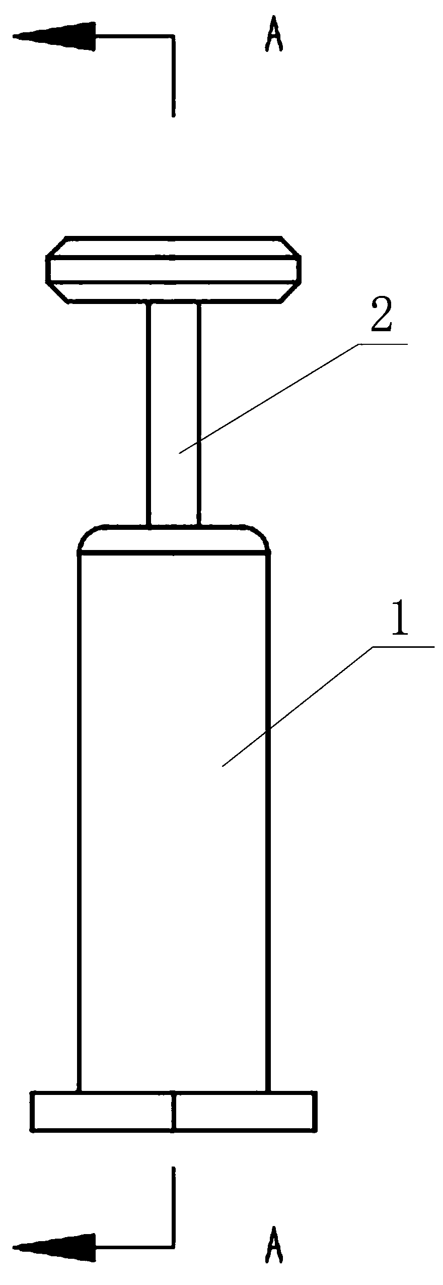
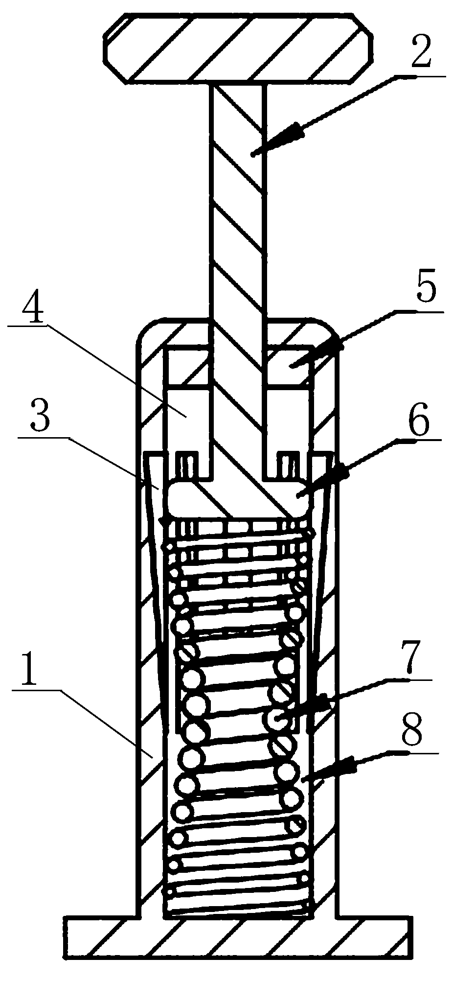
[0025] Such as figure 1 , figure 2 As shown, a hydraulic damping shock absorber with variable stiffness and adaptive variable damping includes a hydraulic cylinder block 1, a tappet 2, a floating piston 6, and a return spring 7; the floating piston 6 is arranged in the hydraulic cylinder block 1 Divide the inner cavity of the hydraulic cylinder 1 into an upper cavity 4 and a lower cavity 8, and make a sealing sliding fit with the inner wall of the hydraulic cylinder 1; the lower end of the tappet 2 passes through the hydraulic cylinder 1 from the top of the hydraulic cylinder 1 It is fixedly connected with the floating piston 6 as a whole; the return spring 7 is arranged in the lower cavity 8, the upper end of the return spring 7 is connected with the floating piston 6, and the lower end is connected with the bottom of the lower cavity 8; the hydraulic cylinder body 1 There are several variable damping grooves 3 distributed circumferentially along the extension direction of ...


PUM


Abstract

The invention discloses a variable rigidity hydraulic damping shock absorber with a self-adaptive variable damping function. The variable rigidity hydraulic damping shock absorber comprises a hydraulic cylinder body, a floating piston, a tappet rod and a return spring; the floating piston is arranged in the hydraulic cylinder body to divide an inner cavity of the hydraulic cylinder body into an upper cavity and a lower cavity and is in sealing sliding fit with the inner wall of the hydraulic cylinder body; the lower end of the tappet rod penetrates through the hydraulic cylinder body from thetop of the hydraulic cylinder body and is fixedly connected with the floating piston into a whole; the return spring is arranged in the lower cavity; the upper end of the return spring is connected with the floating piston; the lower end of the return spring is connected with the bottom of the lower cavity; a plurality of variable damping grooves are circumferentially distributed at the inner partof the hydraulic cylinder body in the length extension direction of the hydraulic cylinder body; and the inner cavity of the hydraulic cylinder body is filled with oil. The variable rigidity hydraulic damping shock absorber can realize self-adaptive damping adjustment; and the return spring which is a concave spiral spring is variable in rigidity to a certain extent, and with the increase of thecompression amount of the spring, the spring can provide greater resistance and can be prevented from being pressed to be stuck, so that the variable rigidity hydraulic damping shock absorber has a certain overload protection function.

Description

technical field [0001] The invention relates to the technical field of damping shock absorbers, in particular to a hydraulic damping shock absorber with variable stiffness and adaptive variable damping. Background technique [0002] The torsional vibration damper of the clutch is one of the important parts of the clutch assembly. Its performance plays an important role in the torsional vibration control of the automobile power transmission system, and it is the main means of clutch vibration reduction. The damping spring on the torsional shock absorber needs to provide a certain stiffness and a certain torsion angle to obtain the transmission torque. At the same time, the torsional shock absorber also needs a certain damping to obtain the damping torque. The sum of the two forms the torsional shock absorber moment. [0003] The reasonable setting of the stiffness and damping torque of the torsional shock absorber is of great significance for the torsional vibration control ...

Claims


Application Information

Patent Timeline
Patent Type & Authority Applications(China)
IPC IPC(8): F16F9/19F16F9/48
CPCF16F9/19F16F9/483
Inventor 刘夫云唐振天耿立冬余汉红胡汝凯张秋峰王秋花
Owner GUILIN UNIV OF ELECTRONIC TECH
Why Eureka
Try Eureka