
Matrix Optical Systems, Condensing Systems and Fly-Eye Lenses

A technology of an optical system and a concentrating system, which is applied in the optical field and can solve the problem of low light intensity.

Active Publication Date: 2020-08-11
TOPLITE INT CO LTD
View PDF7 Cites 0 Cited by
  • Summary
  • Abstract
  • Description
  • Claims
  • Application Information

AI Technical Summary

Problems solved by technology

[0005] Based on this, it is necessary to solve the problem of low light intensity in the traditional matrix optical system, and provide a matrix optical system, a light-condensing system and a fly-eye lens

Method used


Image

  • Matrix Optical Systems, Condensing Systems and Fly-Eye Lenses
  • Matrix Optical Systems, Condensing Systems and Fly-Eye Lenses
  • Matrix Optical Systems, Condensing Systems and Fly-Eye Lenses

Examples


Embodiment Construction

[0029] In order to make the object, technical solution and advantages of the present invention clearer, the present invention will be further described in detail below in conjunction with the accompanying drawings and embodiments. It should be understood that the specific embodiments described here are only used to explain the present invention, not to limit the present invention.

[0030] It should be noted that all technical and scientific terms used herein have the same meaning as commonly understood by those skilled in the technical field of the present invention. The terms used herein in the description of the present invention are for the purpose of describing specific embodiments only, and are not intended to limit the present invention. As used herein, the term "and / or" includes any and all combinations of one or more of the associated listed items.

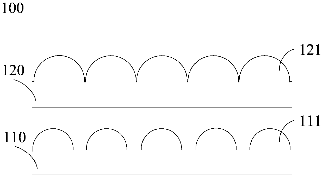
[0031] refer to figure 1 , figure 1 It is a schematic structural diagram of a matrix optical system in an embodiment...


PUM


Abstract

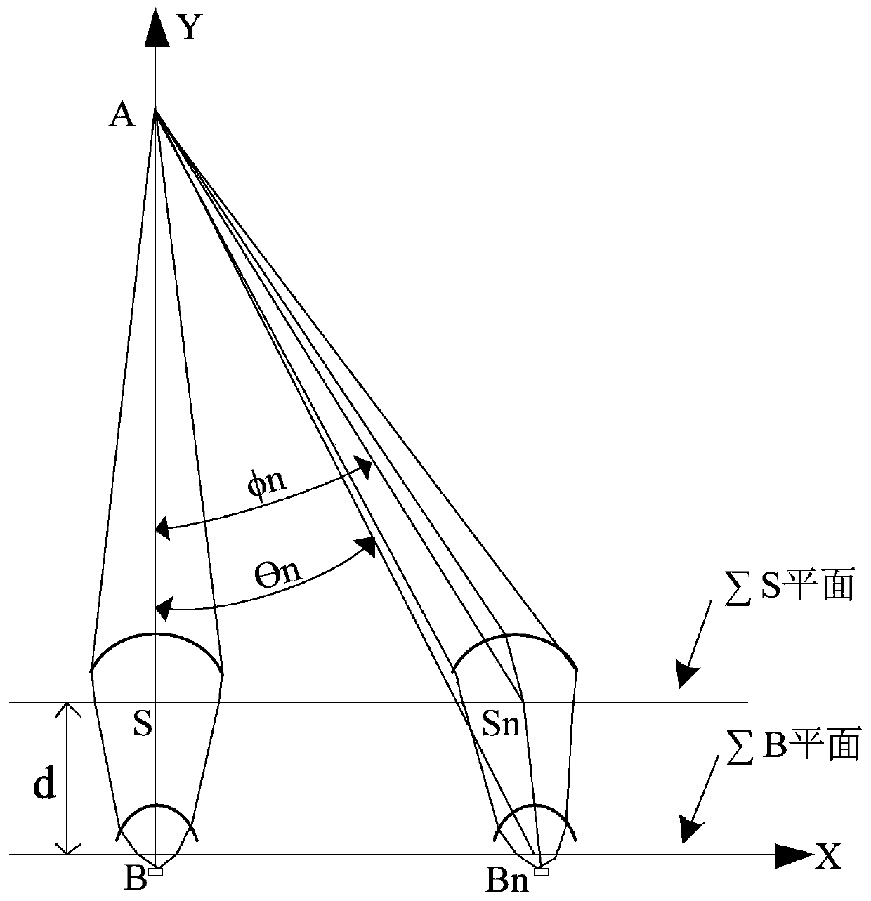
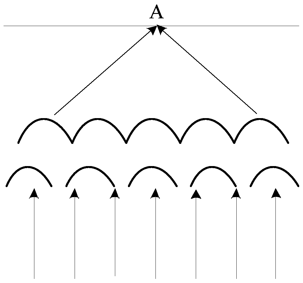
The present invention relates to a matrix optical system, a condensing system and a fly-eye lens. The matrix optical system includes: a first lens and a second lens; the first lens includes a plurality of first lens units; the plurality of first lens units The focal lengths are different; the second lens includes a plurality of second lens units; the focal lengths of the plurality of second lens units are different; the distance between the plurality of first lens units and the distance between the plurality of second lens units Different; the first lens and the second lens are arranged in parallel and spaced apart. Also provided is a condensing system and a fly-eye lens comprising the matrix optical system. By setting the spacing and focal length of the non-coaxial lens units, the above solution can achieve the effect of light concentrating or astigmatism after the light enters the matrix optical system, which enhances the light output intensity of the matrix optical system and improves the light output efficiency of the system.

Description

technical field [0001] The invention relates to the field of optics, in particular to a matrix optical system, a condensing system and a fly-eye lens. Background technique [0002] In the field of optics, in order to meet the requirements of different light sources in different scenarios, more and more optical structures and optical systems have emerged. A matrix light source is a light source that combines multiple dot matrix light sources. It has the characteristics of high luminous intensity and good thermal conductivity, and is widely used in various application fields. In order to make better use of the characteristics of this matrix light source, more and more researchers are trying to design a matrix optical system that can increase light intensity, shorten the optical path, reduce the size of optical devices, and reduce costs. [0003] However, due to its inherent design concept, the traditional matrix optical system still has the problem of low light intensity in p...

Claims


Application Information

Patent Timeline
Patent Type & Authority Patents(China)
IPC IPC(8): G02B3/00G02B19/00
CPCG02B19/0009G02B19/0066G02B3/0037G02B3/0062G02B3/0056G02B19/0014G02B3/0043
Inventor 尹勇健
Owner TOPLITE INT CO LTD
Learn More