
A vacuum circuit breaker and its vacuum interrupter

A vacuum interrupter and vacuum circuit breaker technology, which is applied to high-voltage air circuit breakers, circuits, high-voltage/high-current switches, etc., can solve problems such as circuit breaker reliability degradation, and improve work reliability, reliability, The effect of reducing the mechanical life

Active Publication Date: 2020-10-13
PINGGAO GRP +1
View PDF6 Cites 0 Cited by
  • Summary
  • Abstract
  • Description
  • Claims
  • Application Information

AI Technical Summary

Problems solved by technology

[0004] The purpose of the present invention is to provide a vacuum interrupter to solve the technical problem in the prior art that the reliability of the circuit breaker is reduced due to the consumption of certain operating work by the spring. The present invention also provides a vacuum circuit breaker using the above-mentioned vacuum interrupter

Method used


Image

  • A vacuum circuit breaker and its vacuum interrupter
  • A vacuum circuit breaker and its vacuum interrupter

Examples


Embodiment 1

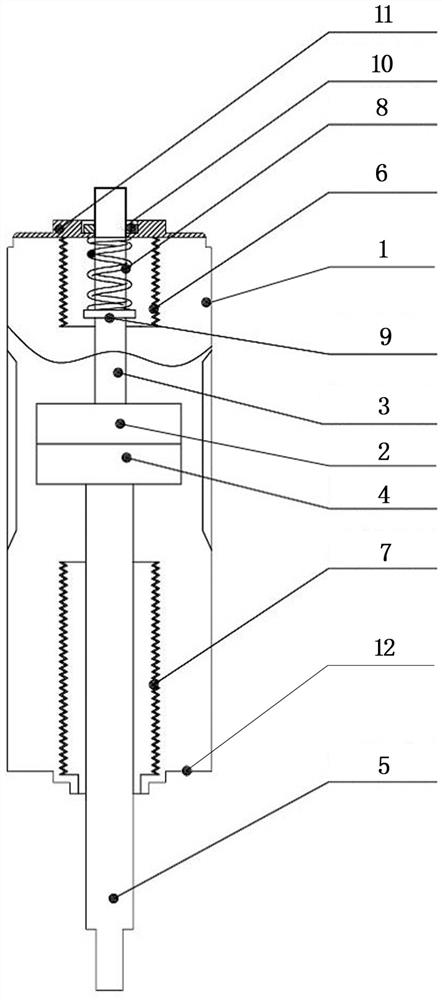
[0025] Such as figure 1 As shown, the vacuum interrupter includes a shell extending in the up and down direction, the shell is a ceramic shell 1, the upper end of the ceramic shell 1 is provided with a static end cover 11 and the lower end is provided with a movable end cover 12, the static end cover 11 and the movable end cover 12 The center is equipped with a static conductive rod 3 and a movable conductive rod 5 corresponding to activities, and the lower end of the static conductive rod 3 and the upper end of the movable conductive rod 5 are correspondingly provided with a static contact 2 and a movable contact 4 . The movable conductive rod 5 is sheathed with a movable end bellows 7 whose upper end is sealed and fixedly connected with the movable conductive rod 5 and whose lower end is sealed and fixedly connected with the movable end cover 12 . A stop ring 9 protrudes from the outer circumference of the static conductive rod 3, and a pressure spring 8 set on the static co...

Embodiment 2

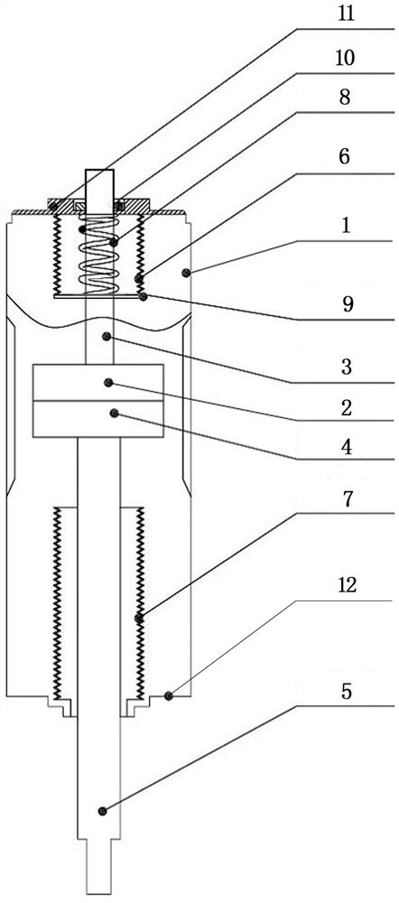
[0031] Such as figure 2 As shown, the main difference between the vacuum interrupter provided in this embodiment and the first embodiment is that the lower end of the bellows 6 at the static end is sealed and fixed on the stop ring 9 . Sealing and fixing the bellows 6 at the static end to the stop ring 9 can save the inner space of the vacuum interrupter, so that the vacuum interrupter can be further miniaturized to adapt to the working occasions with limited space.

Embodiment 3

[0033] The main difference between the vacuum interrupter provided in this embodiment and that in Embodiment 1 is that a longitudinal magnetic field contact is used in this embodiment. At present, there are mainly transverse magnetic field contacts and longitudinal magnetic field contacts with spiral arc running surfaces on the market. The longitudinal magnetic field contacts have better arc extinguishing ability, which can improve the arc extinguishing ability of the vacuum interrupter provided by this embodiment.


PUM


Abstract

The invention relates to a vacuum circuit breaker and a vacuum extinction chamber thereof. The vacuum extinction chamber comprises a housing extending in an up-and-down direction, the two ends of thehousing are correspondingly provided with a static end cover and a moving end cover, a moving conductive rod is movably arranged on the moving end cover, the upper end of the moving conductive rod isprovided with a moving contact, a static conductive rod is elastically assembled in a floating mode in the housing in the up-and-down direction, the lower end of the static conductive rod is providedwith a static contact, the housing is internally provided with a pressure spring applying prepressure to the static conductive rod to compel the static conductive rod to move downwards to allow the moving contact and the static contact to be in contact, and the static conductive rod is sleeved with a static end corrugated pipe having an upper end sealingly and fixedly connected with the static endcover and having a lower end sealingly and fixedly connected with the static conductive rod. The pressure spring is arranged on the static conductive rod to supply prepressure to the contact and conduction of the moving contact and the static contact and avoid the consumption of the operation power supplied by the operating mechanism so as to improve the reliability of the vacuum circuit breaker;and moreover, the arrangement of the static end corrugated pipe reduces the bounce amount of the moving and static contact opening rebound and the closing bounce, and prolongs the mechanical life ofthe static end corrugated pipe.

Description

technical field [0001] The invention relates to a vacuum circuit breaker and its vacuum interrupter. Background technique [0002] The current in the high-voltage line can generate a long arc without extinguishing, so the high-voltage circuit breaker is required to have a perfect arc-extinguishing function. To extinguish the arc, the contact and separation of the dynamic and static contacts in the vacuum interrupter are controlled by the operating mechanism to realize the connection and disconnection of the current of the vacuum circuit breaker. The invention patent application with the application publication number CN106601546A discloses a general-purpose mechanism for protecting vacuum tubes and a vacuum circuit breaker. In the vacuum circuit breaker, a spring connected under the transmission rod is used to provide pre-pressure for the dynamic and static contacts in the vacuum tube to ensure the normal flow. The moving and static contacts are in reliable contact during f...

Claims


Application Information

Patent Timeline
Patent Type & Authority Patents(China)
IPC IPC(8): H01H33/664
CPCH01H33/664
Inventor 毕迎华韩国辉韩桂全张超军卢彦辉姚永琪孙琼
Owner PINGGAO GRP
Learn More