
Method for producing lead frame and lead frame

A technology of lead frame and manufacturing method, which is applied in semiconductor/solid-state device manufacturing, electrical components, electric solid-state devices, etc., and can solve problems such as steps generated by separating chip holders

Active Publication Date: 2019-04-23
MITSUI HIGH TEC INC
View PDF6 Cites 0 Cited by
  • Summary
  • Abstract
  • Description
  • Claims
  • Application Information

AI Technical Summary

Problems solved by technology

In this way, the above-mentioned lead frame including the split die pads may have steps between the split die pads due to the press-down process.

Method used


Image

  • Method for producing lead frame and lead frame
  • Method for producing lead frame and lead frame
  • Method for producing lead frame and lead frame

Examples


Embodiment Construction

[0028] In the following detailed description, for purposes of explanation, numerous specific details are set forth in order to provide a thorough understanding of the disclosed embodiments. It may be evident, however, that one or more embodiments may be practiced without these specific details. In other instances, well-known structures and devices are shown schematically in order to simplify the drawings.

[0029] Embodiments of the present invention described below are examples for explaining the present invention. The present invention should not be limited to the following content.

[0030]

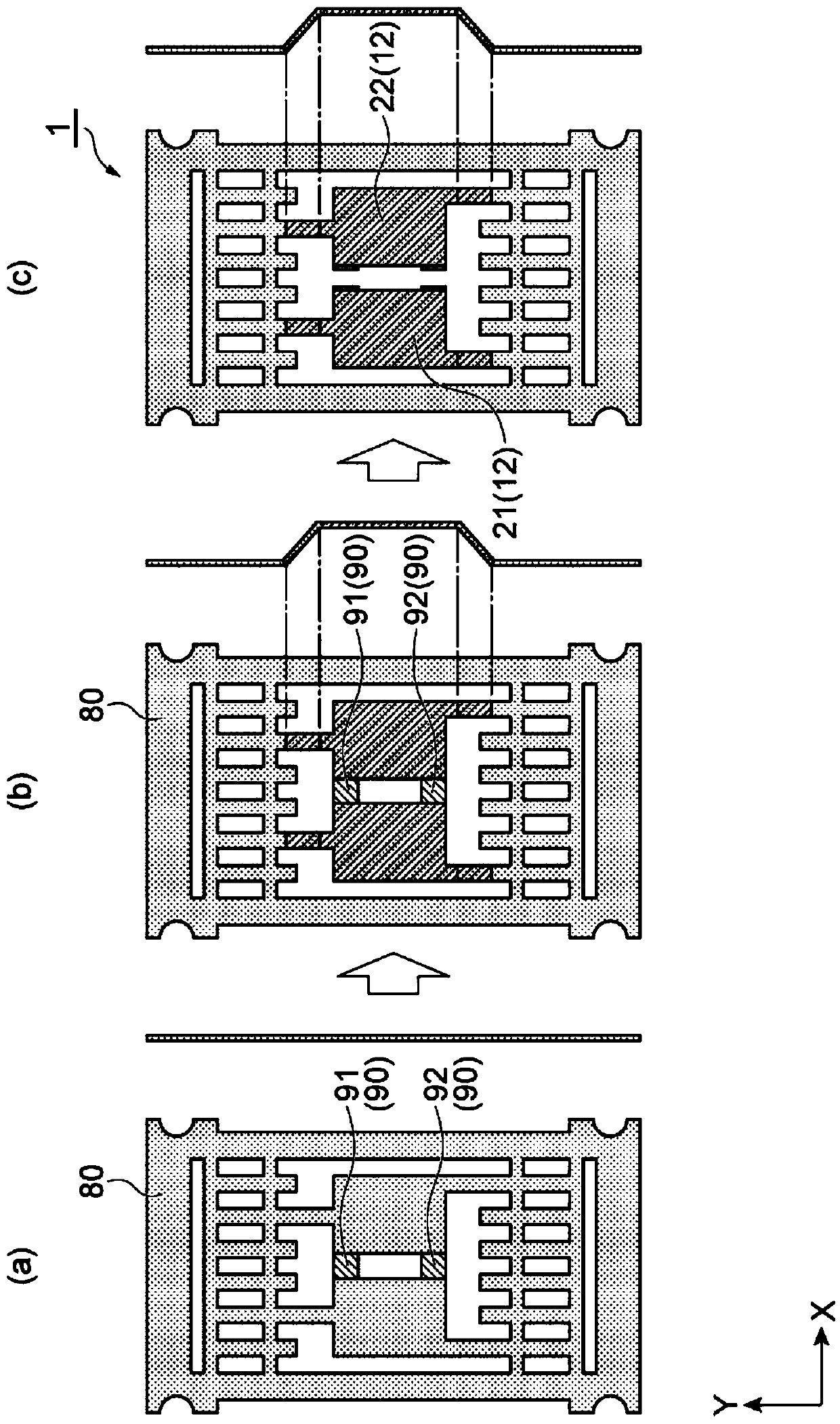
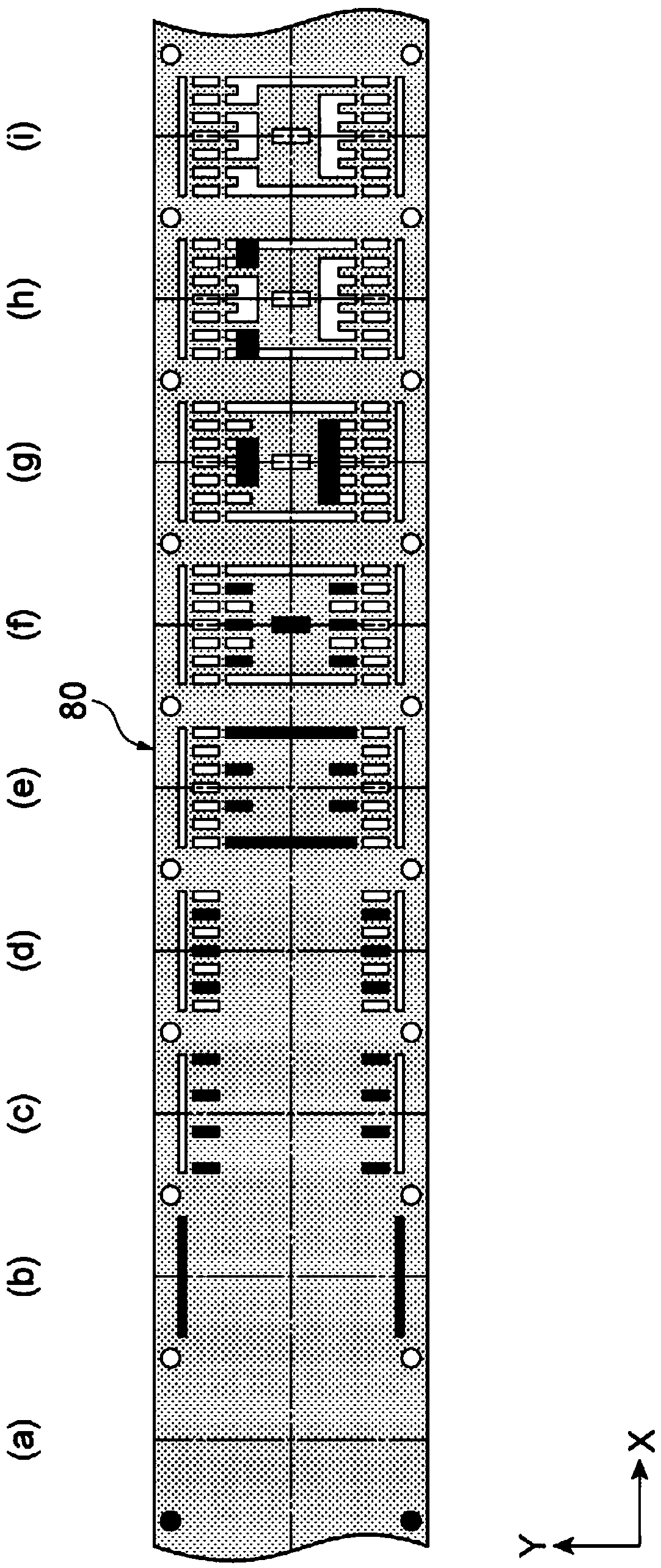
[0031] [1] The method for manufacturing a lead frame according to one embodiment of the present invention includes in sequence: (A) a step of processing a workpiece into the shape of a lead frame including a die pad; (B) pressing down the workpiece the step of processing; and (C) the step of dividing the die pad portion to form separate die pads.

[0032] In the above method of ma...


PUM


Abstract

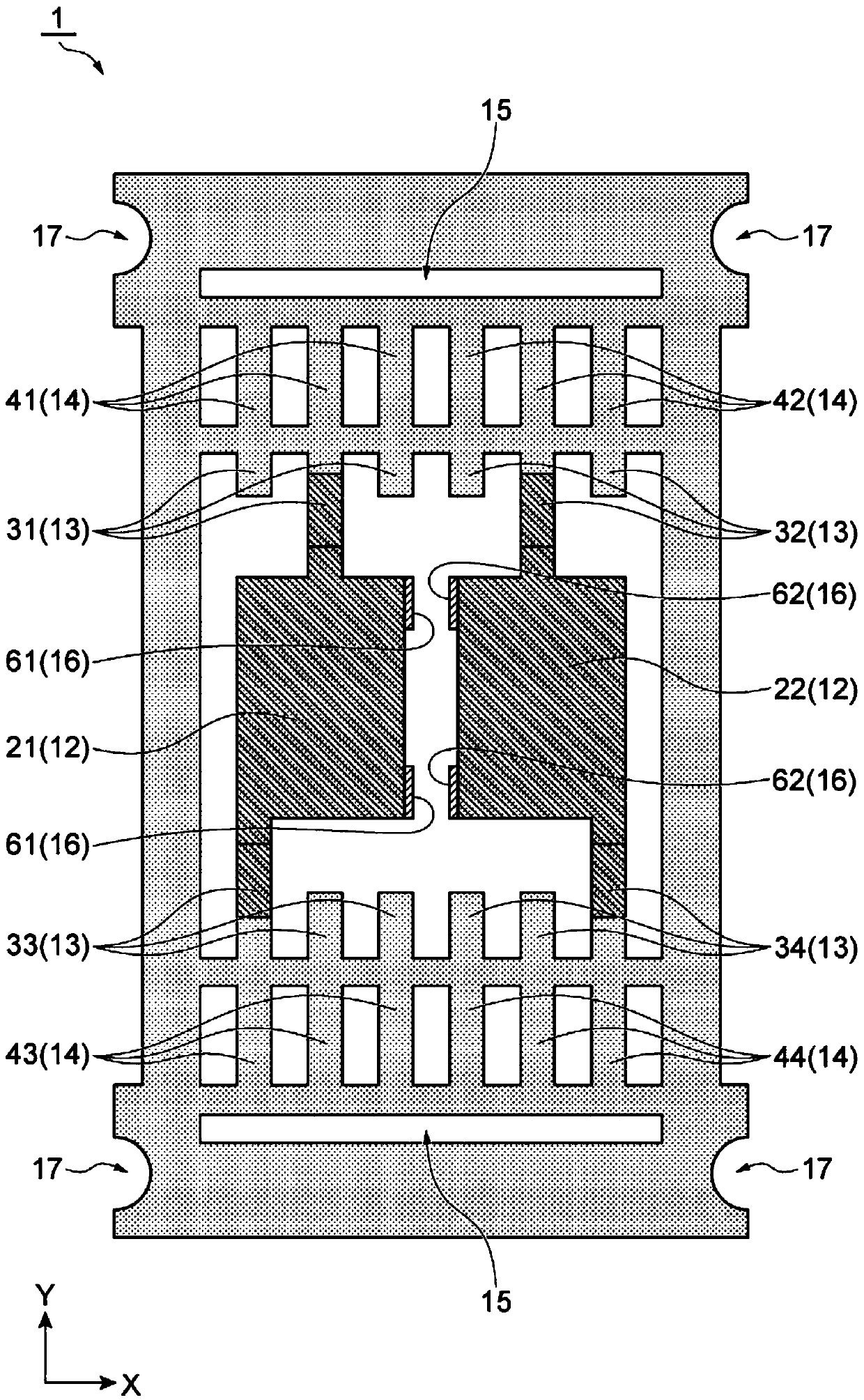
The invention provides a method for producing a lead frame and a lead frame, by which a step cannot be generated between separate chip bases. The method for producing a lead frame (1) according to thepresent invention successively includes, steps of (A) processing a processing material (80) into a shape of a lead frame including a chip base portion, (B) depressing the processing material (80), and (C) dividing the chip base portion to form separate chip bases (21, 22).

Description

technical field [0001] The present invention relates to a method of manufacturing a lead frame and the lead frame. Background technique [0002] Lead frames are used in semiconductor packages to connect semiconductor elements and external wiring. A known lead frame includes a plurality of separate die pads formed by dividing a die pad that supports and fixes a semiconductor element (for example, refer to Japanese Patent Laid-Open Publication No. 2000-22036). [0003] In the manufacturing process of a lead frame, a press process may be performed. In this press-down process, the die pad is displaced downward by a predetermined height so that the semiconductor element mounted on the die pad and the top ends of the inner leads are on the same plane. In this way, the above-mentioned lead frame including the split die pads may have steps between the split die pads due to the press-down process. Contents of the invention [0004] Therefore, in the present invention, a method o...

Claims


Application Information

Patent Timeline
IPC IPC(8): H01L21/48H01L23/495
CPCH01L21/4842H01L23/49541
Inventor 金子政裕饭泉宁
Owner MITSUI HIGH TEC INC
Learn More