Water squeezing structure and cleaning tool

A technology for holding a sink and a broom head is applied in the direction of cleaning carpets, floors, household appliances, etc., to achieve the effects of improving comfort, reducing weight, and reducing labor costs

Pending Publication Date: 2019-04-26
CHANGZHOU INST OF MECHATRONIC TECH
View PDF0 Cites 2 Cited by
  • Summary
  • Abstract
  • Description
  • Claims
  • Application Information

AI Technical Summary

Problems solved by technology

[0005] The second object of the present invention is to provide a cleaning tool to s...

Method used


Image

  • Water squeezing structure and cleaning tool
  • Water squeezing structure and cleaning tool
  • Water squeezing structure and cleaning tool

Examples


Embodiment 1

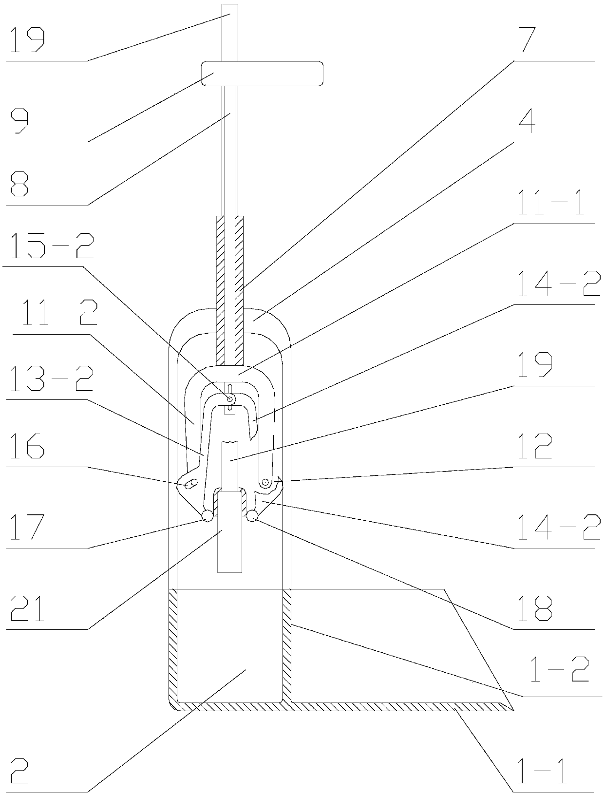
[0050] see Figure 1 to Figure 9 As shown, this embodiment provides a water squeezing structure, including: a water tank 2 suitable for holding water, a connecting frame 4 connected to the water tank 2 and located above the water tank 2, and the connecting frame 4 is far away from the water tank The top of 2 is provided with a guide sleeve 7, a lifting rod 8 pierced in the guide sleeve 7, and a water squeezing assembly that is located at the lifting rod 8 protruding from the side part of the guide sleeve 7 facing the water tank 2.

[0051] Suffice it to say, see Image 6 As shown, the broom head 21 of the broom suitable for the water squeezing structure of this embodiment is made of elastic, porous, and highly water-absorbing materials (such as but not limited to sponge material, water-absorbing fibers, etc.).

[0052] see figure 1 , figure 2 , image 3 As shown, the guide sleeve 7 has a through hole penetrating toward the water tank 2; the lifting rod 8 is inserted into ...

Embodiment approach

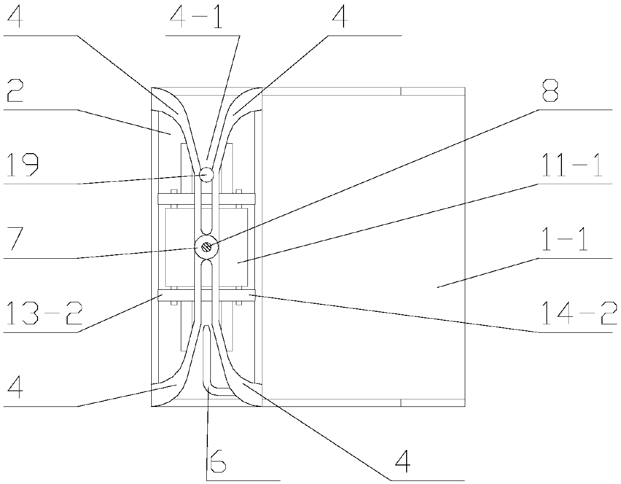
[0067]In an optional embodiment, an elastic clip for fixing the broom head 21 of the broom is provided on the wall plate 2-1 of the water tank 2 away from the clamp groove 4-1 and facing the clamp groove 4-1. The wall plate 2-1 at the place satisfies the requirements for setting the elastic clip, and the height designed for the wall plate 2-1 can be matched with the height of the broom head 21 placed in the accommodating interval of the shift fork, so that the broom head 21 can be inserted into the shift fork. After being placed in the accommodating section, along the length direction of the broom head 21 , one end is fixedly positioned in the clip groove 4 - 1 through the broom handle 19 , while the other end is fixedly positioned in the elastic clip. Here, the wall plate 2 - 1 provided with the elastic clip and the clip groove 4 - 1 extend along the length direction of the broom head 21 to form a positively opposite positional relationship.

[0068] The elastic clip here can...

Embodiment 2

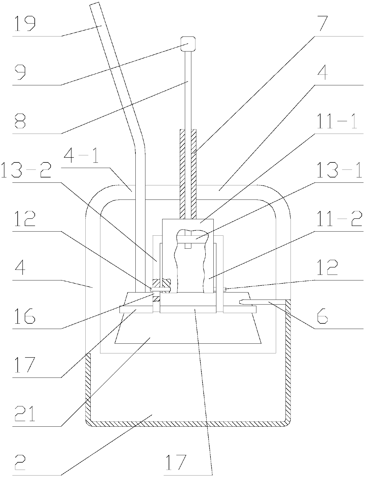
[0074] On the basis of the water squeezing structure of embodiment 1, the water squeezing structure provided by this embodiment is roughly the same as that of embodiment 1, the difference is that please refer to Figure 7 , Figure 8 , Figure 9 As shown, the first extruding assembly of the water squeezing structure of this embodiment includes a first body 13-1 that can rotate around an axis perpendicular to the handle 8, and is integrally connected with the first body 13-1 and is away from the handle 8. A pair of symmetrically arranged first wings 13-2; the first body 13-1 and a pair of first wings 13-2 together form a П-shaped structure; a pair of first wings 13-2 deviate from the first body The end of 13-1 is provided with a first squeezing roller 17.

[0075] see Figure 7 , Figure 8 , Figure 9 As shown, the second extrusion assembly includes a second body 14-1 that can rotate around an axis perpendicular to the handle 8, and a pair of symmetrically arranged first ...


PUM


Abstract

The invention discloses a water squeezing structure and a cleaning tool. The water squeezing structure comprises a water containing groove suitable for containing water, and a connection frame which is connected with the water containing groove and is located above the water containing groove, wherein a guide sleeve, a lifting rod penetrating into the guide sleeve and a water squeezing assembly located at a part, arranged toward one side of the water containing groove, of the lifting rod are arranged at the top, far away from the water containing groove, of the connection frame; the guide sleeve is provided with a through hole which is penetrated toward the water containing groove; the lifting rod is inserted into the through hole and is applicable to up-down movement relative to the watercontaining groove along the through hole; and the water squeezing assembly comprises a shifting fork which is fixedly connected with a part stretching out of the lower side of the guide sleeve of thelifting rod and has a reversed U-shaped structure, and a first squeezing assembly and a second squeezing assembly which are in sliding connection with the part penetrating out of the shifting fork ofthe lifting rod and are suitable for squeezing a broom head from two sides of the broom head respectively.

Description

technical field [0001] The invention relates to the technical field of cleaning tools, in particular to a water squeezing structure and a cleaning tool. Background technique [0002] Tools commonly used when cleaning a home include brooms. In the process of continuous use of the broom, the cleaning effect will be reduced for the dirty broom head, so in order to achieve a better cleaning effect, the broom head needs to be cleaned frequently during cleaning. Generally, the broom head is cleaned with water to clean the broom The purpose of accumulating dust. [0003] Among the commonly used cleaning tools such as the mop, it has its own water-squeezing function, so that the mop can be squeezed to speed up the drying of the mop after cleaning. However, for the broom, very few configurations can squeeze the broom after cleaning. The function of moisture, and compared with the mop with the function of squeezing water, on the one hand, the structure with the function of squeezing...

Claims


Application Information

Patent Timeline
IPC IPC(8): A47L13/60A47L13/52
CPCA47L13/60A47L13/52
Inventor 高志坚徐程刘建国王琳姜海军庞雨花赵海杨兰
Owner CHANGZHOU INST OF MECHATRONIC TECH
Why Eureka
Try Eureka