Novel lightweight automobile hub

A lightweight technology for automobile wheels, applied in the direction of wheels, highly elastic wheels, rims, etc., can solve the problems of small heat dissipation surface of rims, violent body bumps, poor driving comfort, etc., to slow down radial impact, ensure radial support, The effect of slowing down the circumferential impact

Inactive Publication Date: 2019-04-26
河北百龙汽车配件股份有限公司
View PDF7 Cites 0 Cited by
  • Summary
  • Abstract
  • Description
  • Claims
  • Application Information

AI Technical Summary

Problems solved by technology

[0003] The technical problem to be solved by the present invention is to provide a new type of lightweight automobile wheel hub in view of the above-mentioned technical deficiencies. The internal circumference of the rim is uniformly provided with multiple sets of spiral grooves, and the strength of the wheel hub itself is ensured. , multiple sets of spiral grooves are set on the inner surface of the rim, which can not only reduce the weight of the wheel itself, but also make the heat dissipation surface relatively large when the tire conducts heat to the wheel after the car has been driving for a long time. The heavier the rim, the smaller the heat dissipation surface of the rim, resulting in poor heat dissipation; the structure with a drive frame at the center of the outside of the hub is adopted, and the second spring is used to drive the drive frame and the spokes in the circumferential direction, and the drive arm and the spokes are driven longitudinally. The first spring drive makes the hub itself have a good cushioning effect, which can slow down the rigid impact of some grooves on the tire, and solve the problem of severe bumps on the body caused by using flat tires to drive on potholes after the traditional hub is replaced with a larger hub. and poor driving comfort

Method used


Image

  • Novel lightweight automobile hub
  • Novel lightweight automobile hub
  • Novel lightweight automobile hub

Examples


specific Embodiment approach

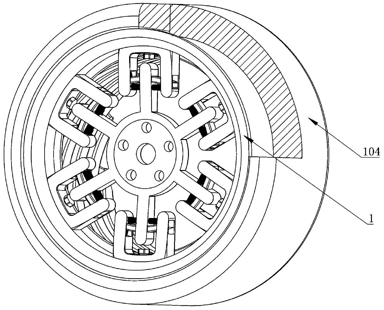
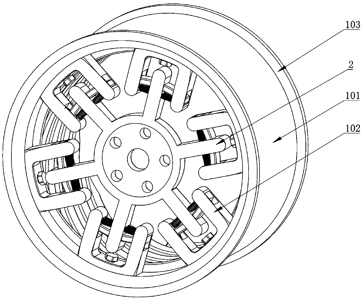
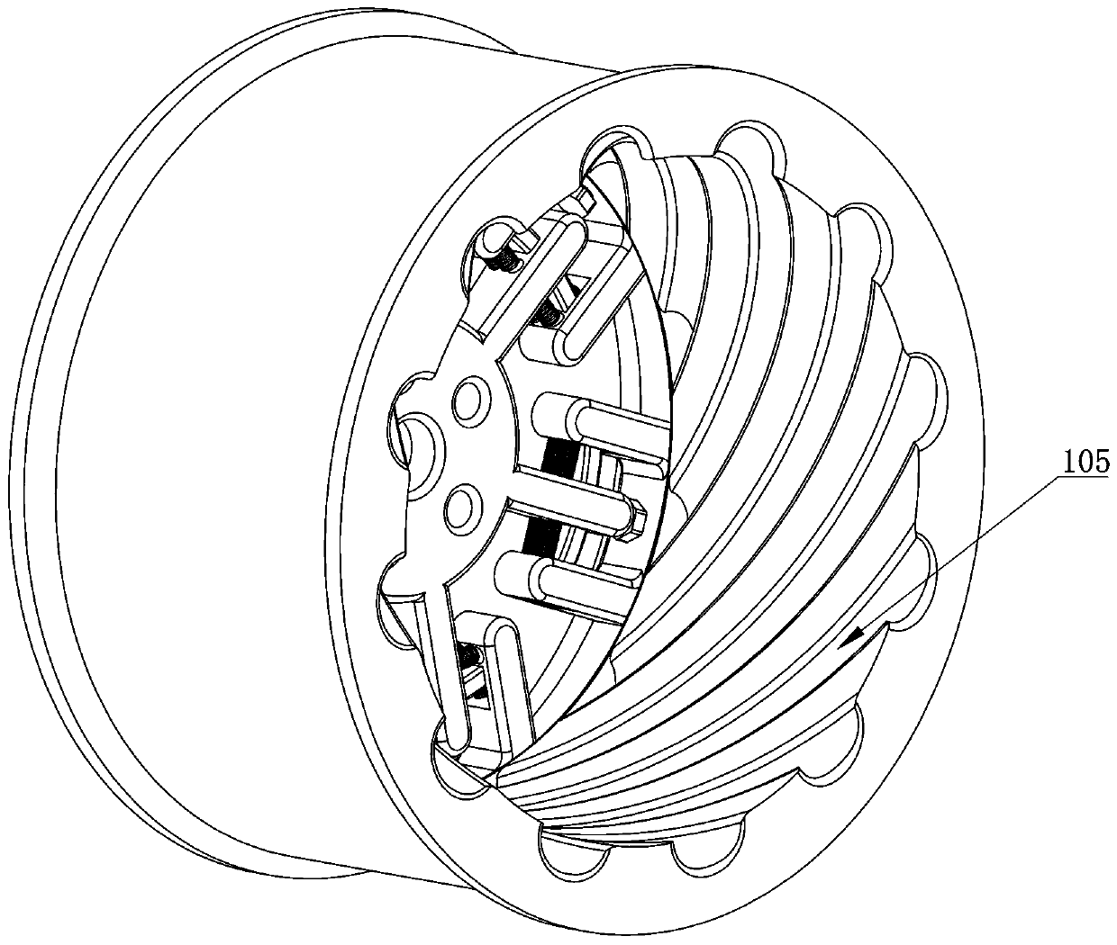
[0016] Specific implementation method: combined Figure 1-5 As shown, it includes a wheel hub 1; the wheel hub 1 includes a rim 101 and a spoke 102; the rim 101 is symmetrically provided with bead seats 103 on both sides in the width direction; the upper part of the rim 101 is provided with a tire 104; respectively clamped with the bead seat 103; the inner circumference of the rim 101 is uniformly provided with multiple sets of spiral grooves 105; one side of the rim 101 is provided with multiple sets of the spokes 102; the spokes 102 and the The rims 101 are connected by bolts; the center position outside the hub 1 is provided with a drive frame 2; the spokes 102 are U-shaped as a whole; First springs 107 are symmetrically arranged on both sides of the inner width direction of the shaped through groove 106; the upper end of the first spring 107 is engaged with the spokes 102; the outer circumference of the transmission frame 2 is evenly provided with multiple groups of transm...


PUM


Abstract

The invention relates to the technical field of hubs and in particular relates to a novel lightweight automobile hub. Multiple groups of spiral grooves are circumferentially and uniformly formed inside the rim. Under the condition that the own strength of the hub is ensured, multiple groups of spiral grooves are formed inside the rim, so that the own weight of the hub can be lightened, the heat dissipation surface is relatively enlarged after long-term automobile driving while conducting heat from the tire to the hub, and the problems that the larger the size of the traditional hub is, the heavier the hub is and the heat dissipation performance is poor due to a small heat dissipation surface of the rim can be solved. With the adoption of the structure that a transmission frame is arrangedat a central position on the outer side of the hub, by virtue of circumferential drive of a second spring between the transmission frame and the spoke and longitudinal drive of a transmission arm anda first spring, the hub achieves an excellent buffering effect, rigid shock of some grooves to the tire can be relieved, and the problems that sharp jolting of the vehicle body and poor driving comfort are caused after the traditional hub is replaced with a big hub and a flat tire drives on a bumpy road can be solved.

Description

technical field [0001] The invention relates to the technical field of wheel hubs, in particular to a novel lightweight automotive wheel hub. Background technique [0002] At present, many car lovers like to replace the wheels with large wheels after buying a car, not only because of the cool appearance of the large wheels, but also because the large wheels have a larger contact area with the ground than the small wheels and have better grip. The disadvantages of the wheel hub are that the size is too large and the weight is too heavy, so it can only be equipped with flat tires, which reduces the driving comfort. Therefore, it is urgent to develop a wheel hub with light weight and cushioning effect. . Contents of the invention [0003] The technical problem to be solved by the present invention is to provide a new type of lightweight automobile wheel hub in view of the above-mentioned technical deficiencies. The internal circumference of the rim is uniformly provided with...

Claims


Application Information

Patent Timeline
Patent Type & Authority Applications(China)
IPC IPC(8): B60B9/02B60B21/12B60B19/10B60B21/00
CPCB60B9/02B60B19/10B60B21/00B60B21/12B60B2900/131B60B2900/513Y02T10/86
Inventor 张彦彬
Owner 河北百龙汽车配件股份有限公司
Why Eureka
Try Eureka