
Intelligent automotive autonomous monitoring system

A monitoring system and smart car technology, applied in the direction of control devices, etc., can solve problems such as endangering the life safety of drivers and passengers, affecting car safety, and the intelligent driving system cannot work normally, so as to achieve the effect of eliminating car failures

Inactive Publication Date: 2019-04-26
JIANGSU KAWEI AUTOMOBILE IND GRP CO LTD
View PDF6 Cites 0 Cited by
  • Summary
  • Abstract
  • Description
  • Claims
  • Application Information

AI Technical Summary

Problems solved by technology

[0002] With the development of science and technology, cars have now become a means of transportation for the public. The number of private cars has increased dramatically. There are a large number of sensors in cars. Most of the sensors used in smart driving cars have a separate automatic correction function. These sensors can detect errors that may be caused by themselves during use and automatically correct them. However, there is currently no unified system To check the status of all the important sensors in the intelligent driving car, this will inevitably lead to the current intelligent driving system may cause the entire intelligent driving system to fail to work properly when a sensor fails. Although the strategy of stopping the work of the intelligent driving system ensures safety, since the state of the sensor may be affected by the intelligent driving car during driving, for the sake of safety, the overall solution of the intelligent driving must include an integrated sensor self-test System, this sensor self-inspection system can not only check the status of each sensor, but also display the inspection results in a specific way. When the car fails, if these faults cannot be found and eliminated in time, it will easily affect the quality of the car. The safety of driving may even endanger the lives of drivers and passengers

Method used


Image

  • Intelligent automotive autonomous monitoring system

Examples


Embodiment Construction

[0018] In order to make the technical solutions of the present invention clearer and clearer to those skilled in the art, the present invention will be further described in detail below in conjunction with the examples and accompanying drawings, but the embodiments of the present invention are not limited thereto.

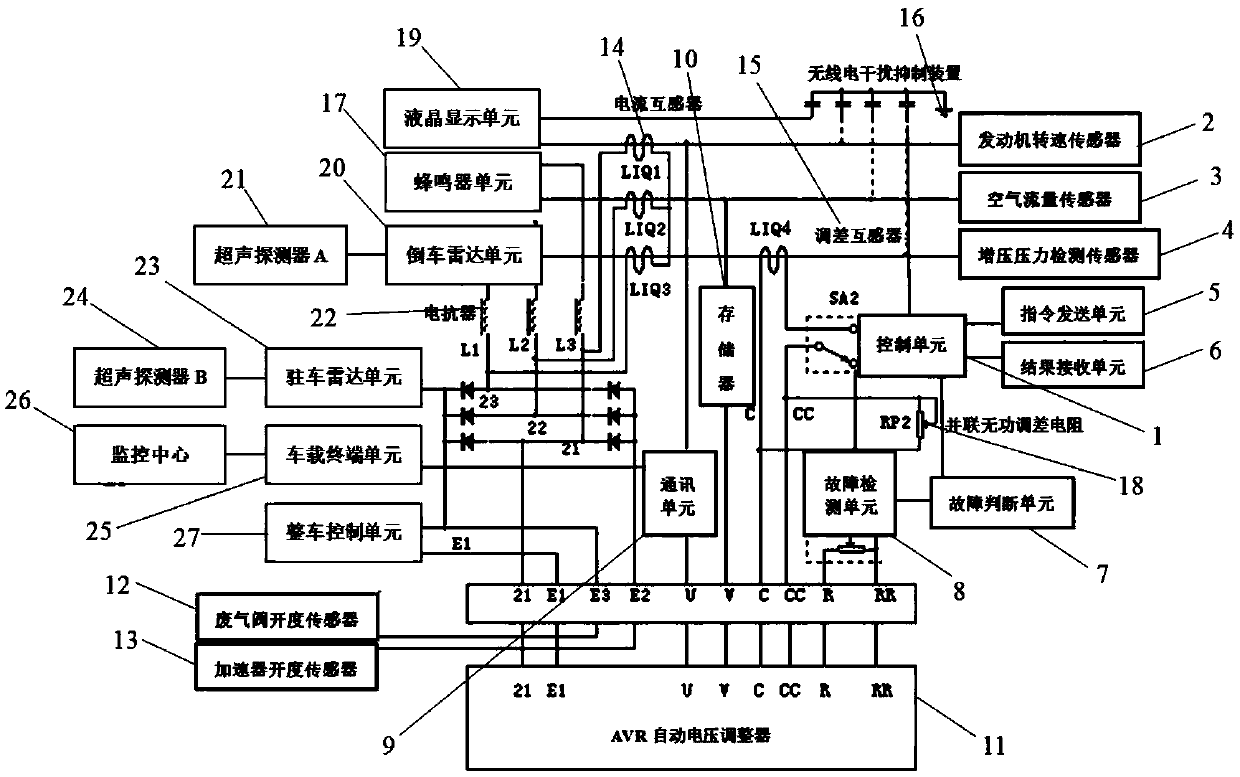
[0019] Such as figure 1 As shown, an autonomous monitoring system for a smart car provided in this embodiment includes a control unit 1, a fault judgment unit 7, a fault detection unit 8, a communication unit 9, a memory 10, a liquid crystal display unit 19, a vehicle terminal unit 25, and a monitoring center 26 and the vehicle control unit 27, the control unit 1 is respectively connected with the fault judgment unit 7, the fault detection unit 8, the communication unit 9, the memory 10, the liquid crystal display unit 19, the vehicle-mounted The terminal unit 25 is electrically connected to the vehicle control unit 27, the vehicle terminal unit 25 is wirelessly co...


PUM


Abstract

The invention discloses an intelligent automotive autonomous monitoring system and belongs to the technical field of automobiles. The system comprises a control unit, a fault judging unit, a fault detecting unit, a communication unit, a memory, a liquid crystal display unit, a vehicle terminal unit, a monitoring center, a vehicle control unit, an AVR (Automatic Voltage Regulator), a waste value opening degree sensor and the accelerator opening degree sensor, wherein the control unit is further respectively connected with an engine speed sensor, an air flow sensor, a boost pressure detecting sensor, a command sending unit, a result receiving unit, a buzzer unit and the liquid crystal display unit; and the communication unit is respectively connected with a car backing radar unit and a parking radar unit. The system disclosed by the invention has the beneficial effects that the faults easily occurring in the automobile are analyzed according to the set fault rules; the fault judgment andthe warning are carried out; the fault types are displayed; the fault information is recorded and stored; and the sensors are checked and the check results are displayed to find and eliminate the faults.

Description

technical field [0001] The invention relates to a vehicle monitoring system, in particular to an intelligent vehicle autonomous monitoring system, which belongs to the technical field of vehicles. Background technique [0002] With the development of science and technology, cars have now become a means of transportation for the public. The number of private cars has increased dramatically. There are a large number of sensors in cars. Most of the sensors used in smart driving cars have a separate automatic correction function. These sensors can detect errors that may be caused by themselves during use and automatically correct them. However, there is currently no unified system To check the status of all the important sensors in the intelligent driving car, this will inevitably lead to the current intelligent driving system may cause the entire intelligent driving system to fail to work properly when a sensor fails. Although the strategy of stopping the work of the intellige...

Claims


Application Information

Patent Timeline
Patent Type & Authority Applications(China)
IPC IPC(8): B60W50/02
CPCB60W50/0205B60W2050/0215
Inventor 孟明华王林飞
Owner JIANGSU KAWEI AUTOMOBILE IND GRP CO LTD
Learn More