
Automatic corner protection feeding pallet type packaging machine

A corner protection and automatic technology, applied in the field of packaging, can solve the problems of reducing manpower, wasting human resources, easy to break and loose bags, etc., and achieve the effect of comprehensive packaging, reducing manpower and saving manpower

Inactive Publication Date: 2019-04-26
广州阿尔法包装系统有限公司
View PDF0 Cites 2 Cited by
  • Summary
  • Abstract
  • Description
  • Claims
  • Application Information

AI Technical Summary

Problems solved by technology

The packaging machinery with steel belt as the material of the packing belt has poor impact resistance and ductility, and the belt is easily broken, and the work efficiency of the packaged items is low. Therefore, the demand for packaging machinery with plastic-steel belt strapping machine is increasing. The baler is a relatively common packaging tool in production packaging. Therefore, before entering the packaging mechanism, the staff needs to press the box by hand, but this method is inefficient and cannot be used for different types of packaging. And the current plastic-steel belt baler can only pack the box in one direction, which cannot meet other balers that need cross-plastic-steel belts.
[0003] Now we provide an automatic upper corner protection sword-piercing baler, which has a more comprehensive packing method and reduces manpower, effectively solving the current low packing efficiency and wasting unnecessary human resources

Method used

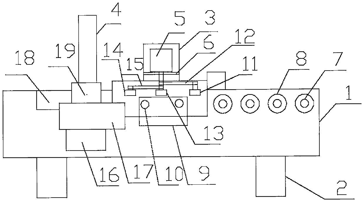
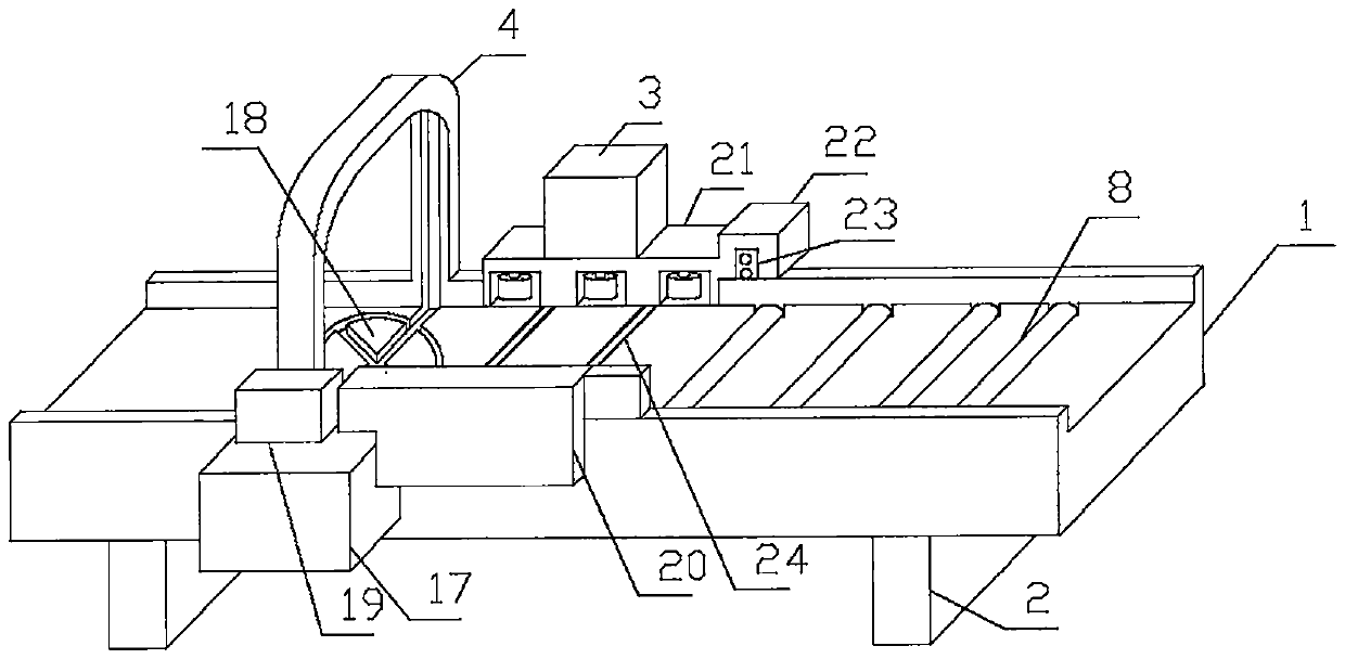

Image

  • Automatic corner protection feeding pallet type packaging machine
  • Automatic corner protection feeding pallet type packaging machine

Examples


Embodiment Construction

[0014] The following will clearly and completely describe the technical solutions in the embodiments of the present invention with reference to the accompanying drawings in the embodiments of the present invention. Obviously, the described embodiments are only some, not all, embodiments of the present invention. Based on the embodiments of the present invention, all other embodiments obtained by persons of ordinary skill in the art without making creative efforts belong to the protection scope of the present invention.

[0015] see Figure 1~2 , in the embodiment of the present invention: a kind of automatic upper angle protector piercing sword type packing machine, comprises frame 1, machine foot 2, machine room 3, packing way 4, baffle plate 6, telescopic room 9, plastic-steel belt room 17, rotating Plate 18, organic feet 2 are fixedly installed at the bottom of frame 1, frame 1 is fixed, and machine feet 2 are used for support. The side wall of frame 1 is fixed with plastic...


PUM


Abstract

The invention discloses an automatic corner protection feeding pallet type packaging machine. The machine comprises a rack, machine feet, a machine chamber, a packaging way, a baffle, and a telescopicchamber; the machine feet are fixedly arranged on the bottom of the rack, a PET strap chamber is fixedly arranged on the side wall of the rack, a PET strap tightening opening is fixedly formed in thetop of the PET strap chamber and is connected with the packaging way, the packaging way is fixedly arranged on the top of the rack, the bottom of the packaging way is connected with a rotating disc,the rotating disc is fixedly arranged on the inner wall of the top of the rack and communicates with the outer wall, the side wall of the rack is fixedly provided with a positioning plate, the positioning plate is arranged on the right side of the PET strap chamber, a wheel groove plate is fixedly arranged on the other side wall of the rack, and corresponds to the positioning plate, the machine chamber is fixedly arranged on the top of the wheel groove plate, and an induction distance measuring chamber is fixedly arranged on the right side wall of the wheel groove plate, and is connected withthe upper wall of the rack. A rotating disc is arranged, when a packaging box reaches the packaging way, cross plastic bags needed by some packaging boxes are subjected to setting and packaging.

Description

technical field [0001] The invention relates to the packing field, in particular to an automatic upper corner-protecting sword-piercing packing machine. Background technique [0002] At present, most of the packaging machinery for metallurgical products in my country uses steel belts as packaging materials, and locks are used for sealing. There is a lack of packaging machinery using plastic steel belts as packaging materials. The packaging machinery with steel belt as the material of the packing belt has poor impact resistance and ductility, and the belt is easily broken, and the work efficiency of the packaged items is low. Therefore, the demand for packaging machinery with plastic-steel belt strapping machine is increasing. The baler is a relatively common packaging tool in production packaging. Therefore, before entering the packaging mechanism, the staff needs to press the box by hand, but this method is inefficient and cannot be used for different types of packaging. A...

Claims


Application Information

Patent Timeline
IPC IPC(8): B65B13/18B65B35/42
CPCB65B13/18B65B35/42
Inventor 叶宇波吕华杰
Owner 广州阿尔法包装系统有限公司
Learn More