
Material melting device

A chemical materializer and chemical barrel technology, applied in the directions of loading/unloading, conveyors, flanged bottle caps, etc., can solve the problems of poor sealing performance, troublesome processing, low production efficiency, etc., and achieve a convenient and fast process. , Improve production efficiency and enhance the effect of sealing

Active Publication Date: 2019-04-26
HUAXIAN DACHAOLIN BUSSAN
View PDF7 Cites 2 Cited by
  • Summary
  • Abstract
  • Description
  • Claims
  • Application Information

AI Technical Summary

Problems solved by technology

[0002] In the process of processing petroleum coke, it is usually necessary to use a feeder. The feeder can obtain some other auxiliary products by heating the petroleum coke, so that the petroleum coke can be fully utilized, resources can be saved, and the utilization rate of resources can be improved. But at present, the structure of the traditional petroleum coke feeder is relatively simple. In order to facilitate the loading of petroleum coke, the feeder is usually just a jar without a cover. After putting the petroleum coke in it, the jar needs to be sent to other heating devices. , and then heating it, the sealing performance is not good, the heat is lost too quickly, and the processing process is more troublesome, resulting in lower production efficiency

Method used


Image

  • Material melting device
  • Material melting device
  • Material melting device

Examples


Embodiment Construction

[0016] The present invention will be described in further detail below in conjunction with the accompanying drawings.

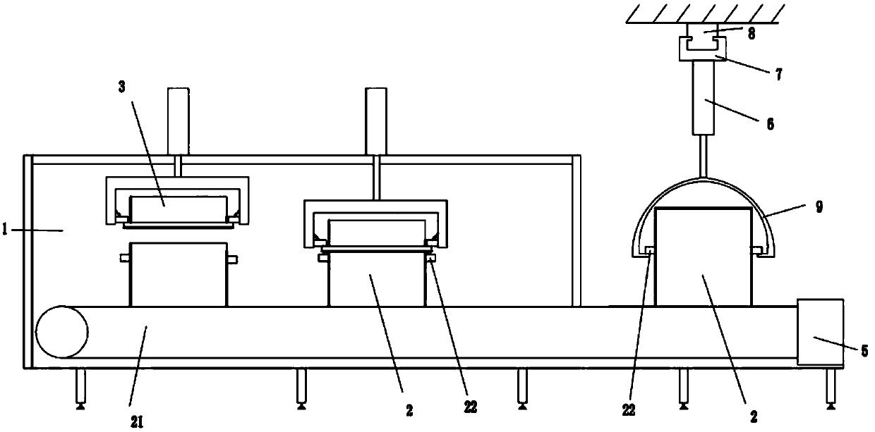
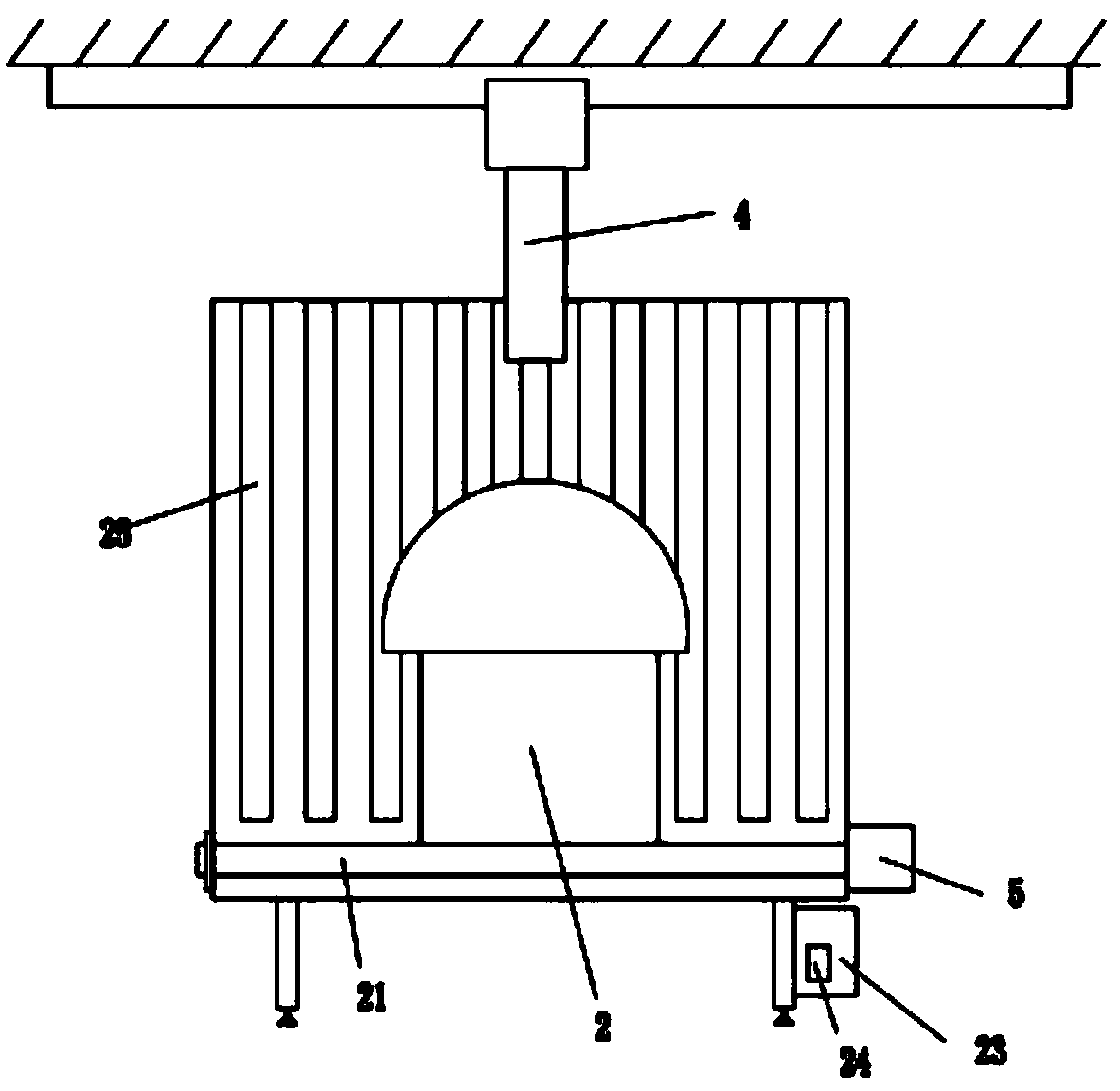
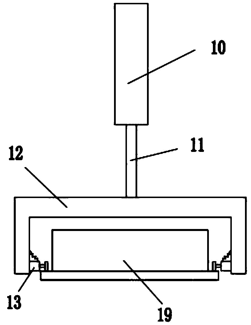
[0017] A chemical feeder, comprising a chemical feed bin 1, a conveyor belt 26 is arranged inside the chemical feed bin 1, a drive motor 5 is provided outside the chemical feed bin 1 to drive the conveyor belt 26 to rotate, and the conveyor belt 26 is provided with There is a chemical material tank 2, and the chemical material tank 1 is provided with a capping device 3 corresponding to the chemical material tank 2, and the capping device 3 includes hangers 12 and cylinders 10 respectively located inside and outside the chemical material tank 1, A lifting rod 11 is provided between the hanger 12 and the cylinder 10, buffer devices 13 are provided on both sides of the hanger 12, and a cover 19 is arranged between the buffer devices 13 on both sides, and the cover 19 passes through the cylinder. 10 Control the lifting rod 11 to drive the hanger 12 to move up and...


PUM


Abstract

The invention discloses a material melting device. A material melting bin is included and internally provided with a conveying belt. A drive motor is arranged at the outer portion of the material melting bin. The conveying belt is provided with a material melting barrel. A cover pressing device is arranged on the material melting bin and comprises a hanging frame and an air cylinder. A lifting rodis arranged between the hanging frame and the air cylinder. Buffering devices are arranged on the two sides of the hanging frame. A cover is arranged between the buffering devices on the two sides, and the cover is used in cooperation with the material melting barrel in the manner that the air cylinder controls the lifting rod to drive the hanging frame to move up and down. An unloading device isarranged at the outlet position of the material melting bin and moves the material melting barrel to the ground. An electric cabinet is arranged on supporting feet at the bottom of the material melting bin and internally provided with a controller, and the air cylinder, a hydraulic support column, an electric sliding block and the drive motor are electrically connected with the controller. Compared with the prior art, the material melting device has the advantages that the structure is simple, operation is convenient, the heat preservation effect is good, meanwhile, the machining process is simple, and the production efficiency is high.

Description

technical field [0001] The invention relates to the technical field of feeders, in particular to a feeder. Background technique [0002] In the process of processing petroleum coke, it is usually necessary to use a feeder. The feeder can obtain some other auxiliary products by heating the petroleum coke, so that the petroleum coke can be fully utilized, resources can be saved, and the utilization rate of resources can be improved. But at present, the structure of the traditional petroleum coke feeder is relatively simple. In order to facilitate the loading of petroleum coke, the feeder is usually just a jar without a cover. After putting the petroleum coke in it, the jar needs to be sent to other heating devices. , and then heating it, the sealing performance is not good, the heat is lost too quickly, and the processing process is more troublesome, resulting in lower production efficiency. Contents of the invention [0003] The technical problem to be solved by the presen...

Claims


Application Information

Patent Timeline
Patent Type & Authority Applications(China)
IPC IPC(8): B67B3/12B65G47/90B65G69/20
CPCB65G47/90B65G69/20B67B3/12B65G2201/0241
Inventor 李广朝李常利王利李铭堂李修宗高一飞
Owner HUAXIAN DACHAOLIN BUSSAN
Learn More