Driving device for automatic thread trimming and automatic presser foot lifting

A driving device and presser foot lifting technology, which is applied in the field of sewing machines, can solve problems affecting the stable operation of sewing machines, loud noises and shaking, etc., and achieve the effects of reliable positioning, reduced shaking and noise, and reduced structure

Active Publication Date: 2019-04-26
ZHEJIANG DUMA SEWING MACHINE
View PDF4 Cites 0 Cited by
  • Summary
  • Abstract
  • Description
  • Claims
  • Application Information

AI Technical Summary

Problems solved by technology

Because the speed of the electromagnet is very different when it is pulled in and when it is bounced off, when the hook thread rod or the presser foot rod moves back and forth, there will often be a loud sound and shaking, which may affect the stable operation of the sewing machine

Method used


Image

  • Driving device for automatic thread trimming and automatic presser foot lifting
  • Driving device for automatic thread trimming and automatic presser foot lifting
  • Driving device for automatic thread trimming and automatic presser foot lifting

Examples


Embodiment 1

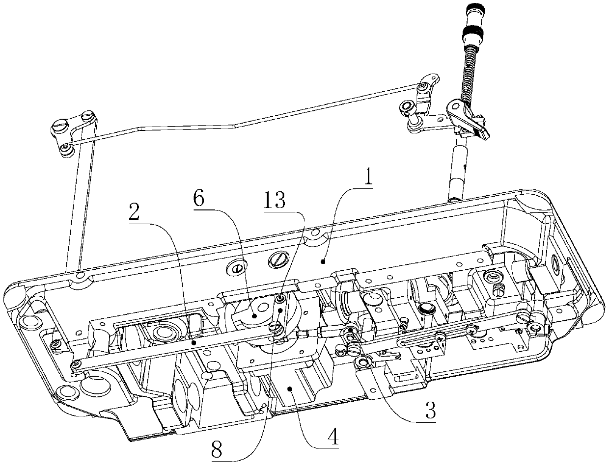
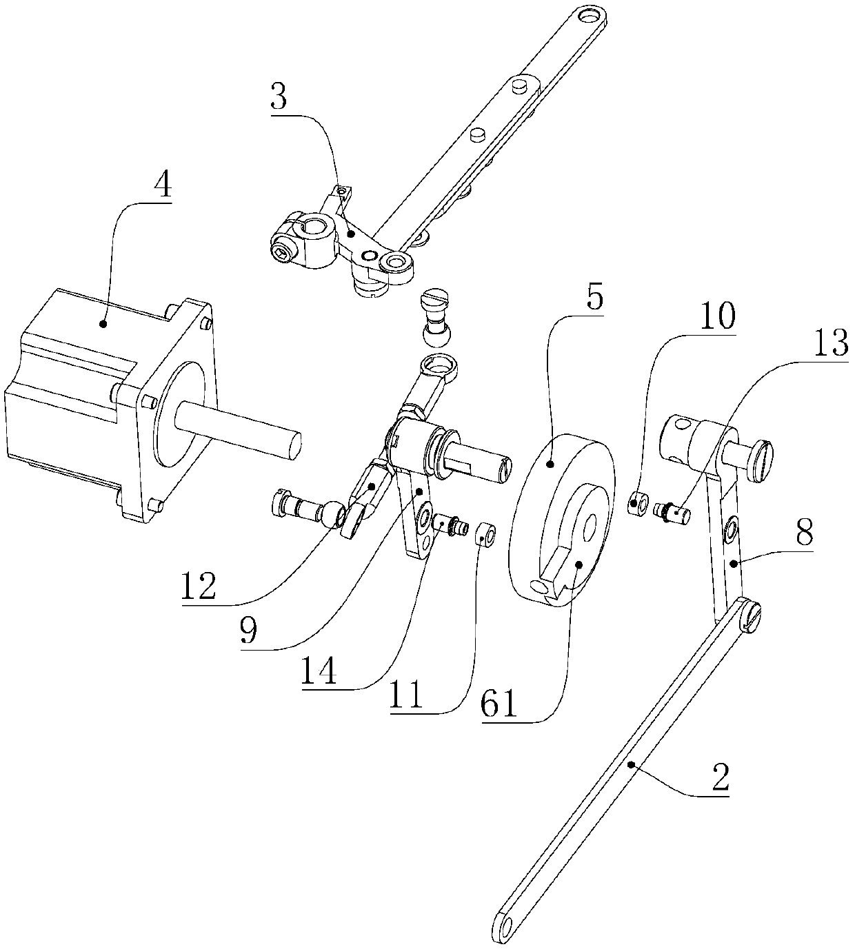
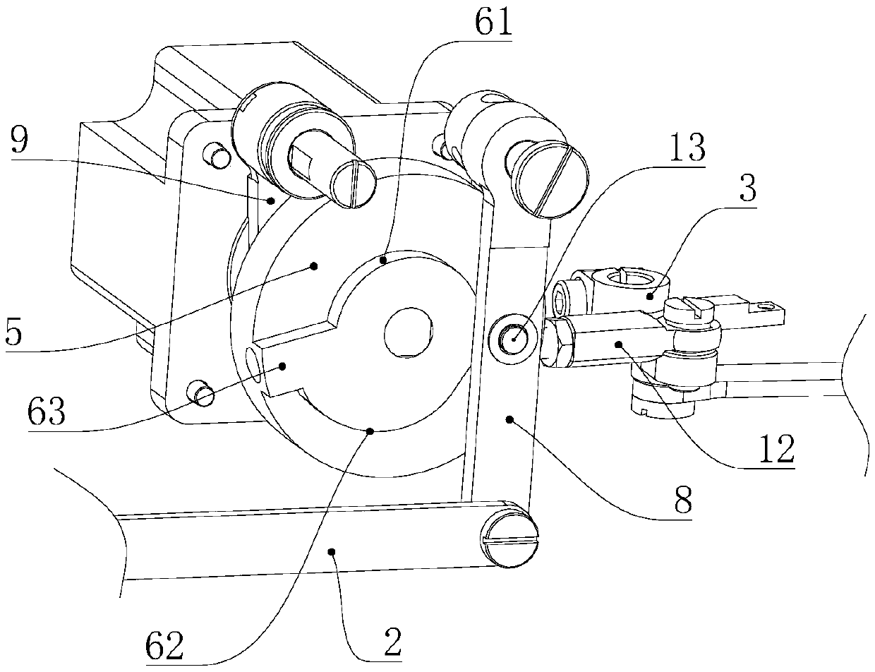
[0031] see Figure 1 to Figure 6 As shown, a driving device for automatic thread trimmer and automatic presser foot lifter includes a presser foot lifter drive rod 2, a thread trimmer drive rod 3, a stepper motor 4, a cam body 5, a presser foot lifter connecting rod 8 and a thread trimmer connection Rod 9, the cam body 5 is arranged on the output shaft of the stepping motor 4; the cam body 5 is provided with a presser foot lifting drive cam 6 and a thread trimmer drive cam, and one end of the presser foot lifting connecting rod 8 is hinged On the sewing machine housing 1, the other end of the presser foot lifter connecting rod 8 is hinged to one end of the presser foot lifter transmission rod 2, and the presser foot lifter connecting rod 8 is also provided with a first driven pin 13, the first driven pin 13 Slide along the presser foot driving cam 6; one end of the thread trimming connecting rod 9 is hinged on the sewing machine housing 1, the other end of the thread trimming ...

Embodiment 2

[0048] This embodiment is basically the same as the first embodiment, the difference is that: the presser foot lifting driving cam 6 and the thread trimming driving cam are independent cam bodies.

[0049] In addition, the relative installation positions of the drive cam and the driven pin can also be interchanged, such as: the thread trimmer connecting rod 9 is provided with a thread trimmer drive cam, and the thread trimmer drive cam is an inwardly concave track groove 7; The output shaft of the feeder 4 is provided with a second driven pin 14, and one end of the second driven pin 14 is provided with a rotatable second runner 11, and the second runner 11 is adapted to the track groove 7, so The second runner 11 reciprocates along the inner wall of the track groove 7 .


PUM


Abstract

The invention belongs to the technical field of sewing machines and in particular discloses a driving device for automatic thread trimming and automatic presser foot lifting with advantages of being simple in structure and capable of ensuring steady operation of the sewing machine. The driving device comprises a presser foot lifting transmission bar, a trimming transmission bar, a stepping motor,a cam body, a presser foot lifting connecting rod and a thread trimming connecting rod, wherein the cam body is arranged on the stepping motor; a presser foot lifting driving cam surface and a threadtrimming driving cam surface which respectively comprise a base circle surface and a lift curved surface are arranged on the cam body; the other end of the presser foot lifting connecting rod is hinged to one end of the presser foot lifting transmission bar; a first follower pin is arranged on the presser foot lifting connecting rod; the trimming transmission bar is hinged to the other end of thetrimming transmission bar; a second follower pin is arranged on the thread trimming connecting rod; when the stepping motor clockwise drives the cam body by a certain angle, one follower pin enters the lift curved surface from the base circle surface, and the other follower pin slides on the base circle surface; and when the stepping motor anticlockwise rotates, the other follower pin enters the lift curved surface from the base circle surface, and the one follower pin slides on the base circle surface.

Description

[0001] This application is a divisional application of "A Drive Device for Automatic Thread Trimming and Automatic Presser Foot Lifting" with application number 2016106141869 and application date 2016.07.30. technical field [0002] The invention belongs to the technical field of sewing machines, and specifically refers to a driving device for automatic thread trimmer and automatic presser foot lifter. Background technique [0003] At present, the thread hook lever used for thread trimming and the presser foot lever used for lifting the presser foot on the sewing machine are respectively controlled by two electromagnets. When the presser foot needs to be lifted, another electromagnet controls the presser foot pull bar to move back and forth. Because the speed of the electromagnet is very different when it is engaged and when it is bounced off, when the thread hook lever or the presser foot lever moves back and forth, there will often be loud noises and shaking, which may aff...

Claims


Application Information

Patent Timeline
Patent Type & Authority Applications(China)
IPC IPC(8): D05B29/02D05B65/00D05B69/10
CPCD05B29/02D05B65/00D05B69/10
Inventor 阮孟定
Owner ZHEJIANG DUMA SEWING MACHINE
Why Eureka
Try Eureka