
Rapid transfer method and equipment of super-large bridge girder erection machine for assembled steel-concrete composite bridge

A transfer method and technology of a bridge erecting machine, which are applied in the erection/assembly of bridges, bridge construction, bridges, etc., can solve the problems of multiple time and consumption, shorten the construction period, save the construction cost, and save the time of repeated disassembly and assembly. and cost effects

Active Publication Date: 2019-04-26
HAIOD HEAVY ENG TECH
View PDF13 Cites 5 Cited by
  • Summary
  • Abstract
  • Description
  • Claims
  • Application Information

AI Technical Summary

Problems solved by technology

[0004] In order to solve the deficiencies of the prior art, the present invention provides a method and equipment for fast transfer of a super-large bridge erecting machine for an assembled steel-concrete composite bridge, which can solve the overall luffing erection of the bridge erecting machine encountered in the on-site girder erection of the traditional bridge erecting machine , the overall passage through the tunnel, the overall return to the starting point, the overall forward transfer to the next installation site and other working conditions, the disassembly and assembly transfer method consumes a lot of time, manpower, material resources and financial resources.

Method used


Image

  • Rapid transfer method and equipment of super-large bridge girder erection machine for assembled steel-concrete composite bridge
  • Rapid transfer method and equipment of super-large bridge girder erection machine for assembled steel-concrete composite bridge
  • Rapid transfer method and equipment of super-large bridge girder erection machine for assembled steel-concrete composite bridge

Examples


Embodiment Construction

[0054] The present invention will be further described below in conjunction with drawings and embodiments.

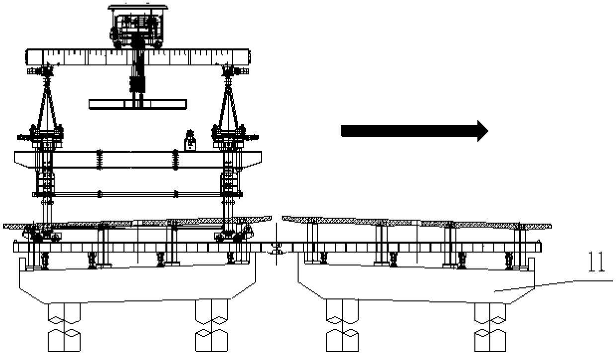
[0055] The present invention provides a whole rapid transfer method of a super-large bridge erecting machine for an assembled steel-concrete composite bridge, referring to Figure 1 to Figure 16 , including the following steps:

[0056] (1) The bridge erecting machine 1 is ready to be transported after the girder erection of the first bridge width is completed, and the bridge erection machine 1 is driven to the middle position of the pier, and the bridge erection machine 1 is moved laterally to the top of the second bridge width;

[0057] (2) Install the special tooling beam 2 for transfer on the beam transport vehicle 6 of the first bridge width through the connection base 3, set the anti-overturning outriggers 4 at both ends of the special tooling beam 2 for transfer, and set the auxiliary scroll wheel;

[0058] (3) Drive the beam transporter 6 to the position betwe...


PUM


Abstract

The invention provides a rapid transfer method and equipment of a super-large bridge girder erection machine for an assembled steel-concrete composite bridge. The rapid transfer of the bridge girder erection machine is realized by using a front folding leg, a fixture crossbeam special for transferring and an anti-overturning leg. The involved equipment is simple in structure and high in transfer efficiency; when the bridge girder erection machine encounters the working conditions that the bridge girder erection machine performs integrated amplitude-change erection, integrally passes through atunnel, integrally returns to a starting point and integrally advances and transfers to the next installation location, the operations that the bridge girder erection machine performs integrated amplitude-change erection, integrally passes through the tunnel, integrally returns to the starting point and integrally advances and transfers can be completed without dismantling the main body of the bridge girder erection machine, thereby saving the construction cost, accelerating the construction progress and reducing the safety risk. The rapid transfer method and equipment of the super-large bridge girder erection machine for the assembled steel-concrete composite bridge are suitable for erection and installation of the assembled steel-concrete composite bridge and can be also applied to otherfields of similar structure types.

Description

technical field [0001] The invention relates to a fast transfer method and equipment for a super-large bridge erecting machine of an assembled steel-concrete composite bridge, which belongs to the field erection and installation equipment transfer technology for large-scale components, and is mainly used in the overall rapid variable-amplitude erection of super-large bridge erecting machines and the rapid passage of tunnels as a whole , the overall rapid return to the starting point, the overall rapid transfer to the next installation site, and can also be applied to other fields of similar structure types. Background technique [0002] Prefabricated steel bridges have been widely used all over the world. Bridges can be divided into reinforced concrete girder bridges, prestressed concrete girder bridges, steel structure girder bridges and concrete and steel composite structure girder bridges according to the different materials used. Reinforced concrete girder bridges mostly...

Claims


Application Information

Patent Timeline
Patent Type & Authority Applications(China)
IPC IPC(8): E01D21/00
CPCE01D21/00
Inventor 吕正东叶顺陈文强
Owner HAIOD HEAVY ENG TECH
Learn More