
A debugging equipment and electronic equipment

A technology of electronic equipment and equipment, applied in software testing/debugging, electrical digital data processing, instruments, etc., can solve problems such as time cost and maintenance cost of disassembly and debugging scheme, and achieve high time cost and maintenance cost, easy to use and easy to use. The effect of on-site debugging

Inactive Publication Date: 2019-04-26
ZHENGZHOU YUNHAI INFORMATION TECH CO LTD
View PDF3 Cites 2 Cited by
  • Summary
  • Abstract
  • Description
  • Claims
  • Application Information

AI Technical Summary

Problems solved by technology

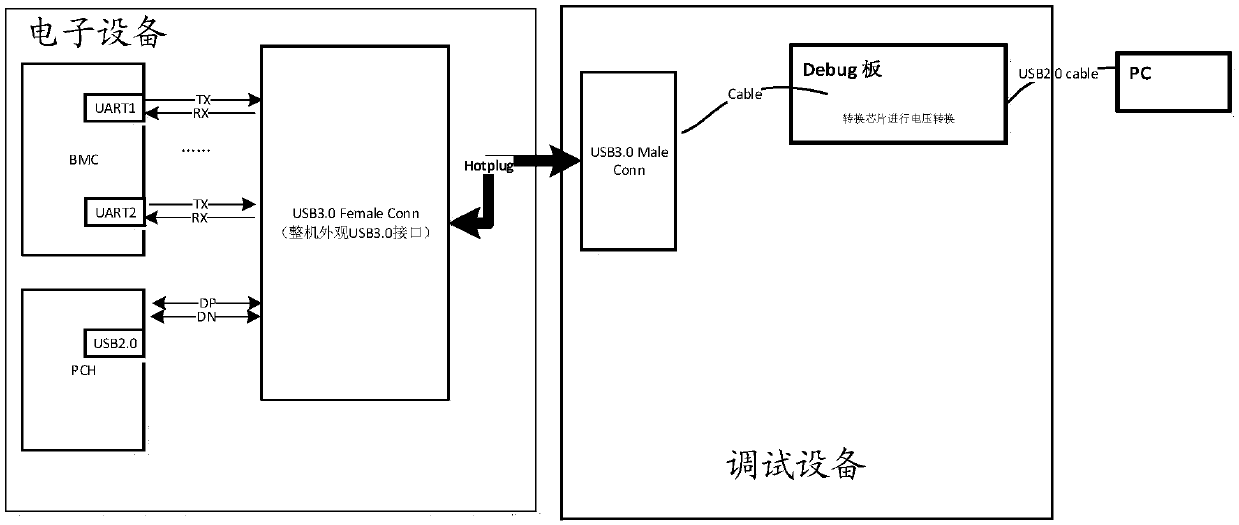
By adding a male header that matches the existing interface of the electronic device to be debugged on the Debug device, the connection between the debug device and the electronic device can be completed without disassembling the device, which greatly improves the usability of the debug device and solves the problem of disassembly The problem of high time cost and maintenance cost of debugging scheme

Method used


Image

  • A debugging equipment and electronic equipment
  • A debugging equipment and electronic equipment
  • A debugging equipment and electronic equipment

Examples


Embodiment Construction

[0020] In order to make the purpose, technical solution and advantages of the present invention more clear, the embodiments of the present invention will be described in detail below in conjunction with the accompanying drawings. It should be noted that, in the case of no conflict, the embodiments in the present application and the features in the embodiments can be combined arbitrarily with each other.

[0021] The steps shown in the flowcharts of the figures may be performed in a computer system, such as a set of computer-executable instructions. Also, although a logical order is shown in the flowcharts, in some cases the steps shown or described may be performed in an order different from that shown or described herein.

[0022] Existing server designs must be disassembled to complete. For consumer electronic products with complex structures, the disassembly process is very complicated, and it is easy to cause damage to the structural parts of the whole machine. The disass...


PUM


Abstract

The invention discloses debugging equipment and electronic equipment. The invention relates to an electronic circuit technology, and solves the problems of high time cost and maintenance cost of a disassembling debugging scheme. The debugging equipment comprises a Debug board, wherein the Debug board is connected with a male head which extends out of the debugging equipment and is matched with anexternal interface of electronic equipment to be debugged, and the male head is connected to the external interface of the electronic equipment to be debugged during debugging, so that the connectionbetween the Debug board of the debugging equipment and the electronic equipment to be debugged is completed. The technical scheme provided by the invention is suitable for debugging the electronic product after leaving the factory, and easy-to-use and convenient electronic product on-site debugging is realized.

Description

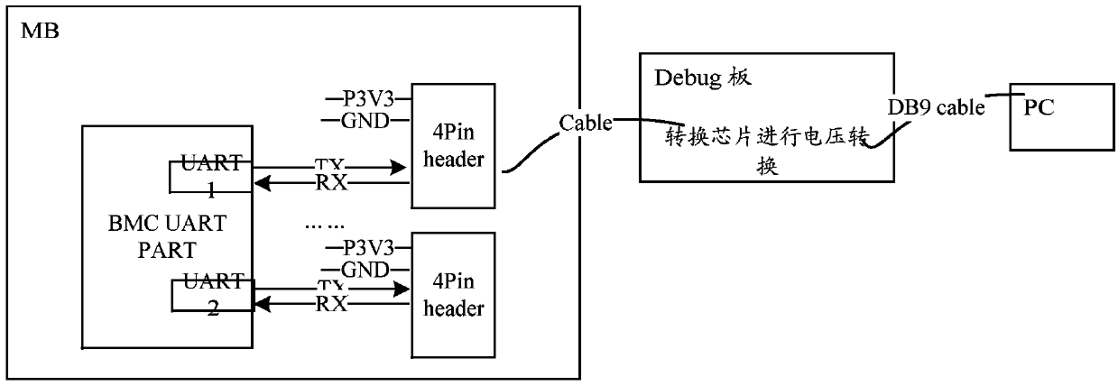
technical field [0001] The invention relates to electronic circuit technology, in particular to a debugging device and an electronic device. Background technique [0002] As the functions and performance of servers and other consumer electronic products continue to increase, the interface design and miniaturization requirements of their appearance make it impossible to have an additional Debug interface on the appearance. [0003] Due to the design of the product’s external interface without Debug, if there is an abnormal state such as downtime during the customer’s on-site use, the Uart interface must be connected to the Uart interface to read the relevant Log information by disassembling the machine, and its operability and maintenance functions will be lost. kind of hard. [0004] In the existing server design, the signal directly connected to the UART module of the BMC chip at the control end is connected to an external header (including SYS UART and BMC UART). During ...

Claims


Application Information

Patent Timeline
Patent Type & Authority Applications(China)
IPC IPC(8): G06F11/36G06F13/42
CPCG06F11/3648G06F11/3656G06F13/4282
Inventor 刘纪斌孙博苗
Owner ZHENGZHOU YUNHAI INFORMATION TECH CO LTD
Learn More