
A GPU line rasterization boundary calculation optimization method

An optimization method and rasterization technology, which can be used in calculations, filling planes with attributes, instruments, etc., and can solve problems such as insignificant error effects.

Active Publication Date: 2019-04-26
XIAN AVIATION COMPUTING TECH RES INST OF AVIATION IND CORP OF CHINA
View PDF2 Cites 1 Cited by
  • Summary
  • Abstract
  • Description
  • Claims
  • Application Information

AI Technical Summary

Problems solved by technology

When drawing a straight line alone (without a reference object), the error effect is not obvious; but when drawing a straight line continuously, or drawing an arc with a small straight line, the visual effect caused by the error is unacceptable, and these need to be solved technical problem

Method used


Image

  • A GPU line rasterization boundary calculation optimization method

Examples


Embodiment

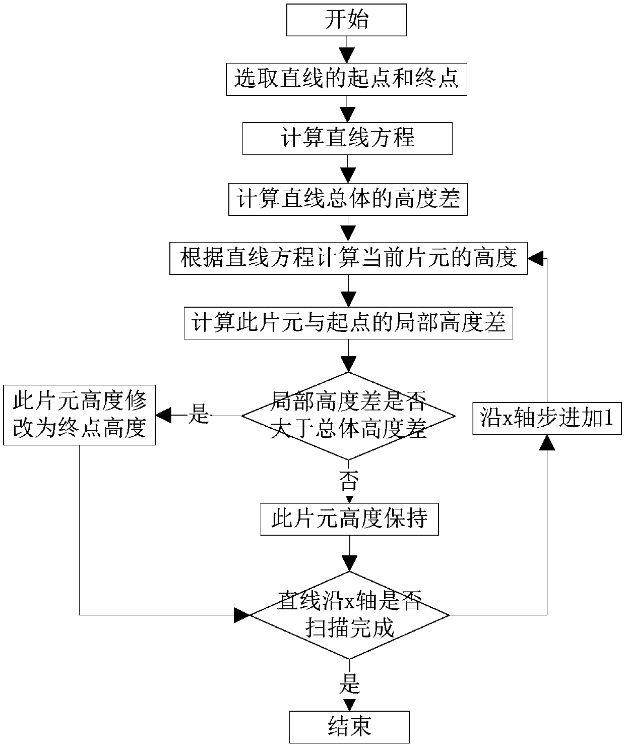
[0034] Below in conjunction with accompanying drawing the present invention is described in further detail, please refer to figure 1 .

[0035] A GPU line rasterization boundary calculation optimization method, comprising the following steps:

[0036] Step 1. Select the starting point and end point of the straight line. Select the starting point and end point of the straight line, and also specify the scanning direction of the straight line. Generally, choose to scan from the low point to the high point. When the height of the starting point and the end point are the same, select the scanning direction from the left to the right.

[0037] Step 2. Calculation of the straight line equation. According to the selected end point and starting point, the straight line equation can be calculated: y=kx+b, where k is the slope and b is the intercept.

[0038] Step 3, calculate the height difference of the straight line, calculate the height difference between the starting point and th...


PUM


Abstract

The invention relates to the technical field of computer hardware modeling, and provides a GPU (Graphics Processing Unit) line rasterization boundary calculation optimization method, which comprises the following steps of: 1, selecting a starting point and an end point of a straight line, and selecting the starting point and the end point of the straight line; 2, calculating the height of each chip element, and calculating the height of each chip element according to a linear equation when a straight line is scanned; Step 3, calculating the height difference between each chip element and the starting point, keeping the height of the straight line starting point, and calculating the height difference between the current chip element and the starting point according to the height value obtained in the previous step; And 4, boundary comparison: comparing the height difference calculated in the step 3 with the overall height difference of the straight line: when the height difference is greater than the overall height difference of the straight line, modifying the height of the sheet element to be the final height, otherwise, keeping the height of the sheet element. The method solves the problem that the height threshold value substituted by error accumulation exceeds, especially the problem that the intersection points of adjacent lines are not uniform during continuous line drawing, and optimizes the GPU line rasterization algorithm.

Description

technical field [0001] The invention relates to the technical field of computer hardware modeling, in particular to a calculation optimization method for GPU line rasterization boundaries. Background technique [0002] Graphics processor chips (hereinafter referred to as GPUs) generally step by step and scan along the x-axis or y-axis when rasterizing line primitives, but the step units of the x-axis and y-axis in the rasterization stage are fragments, so The calculated height value can only be rounded up. There must be errors when rasterizing a straight line. When the scan reaches a certain length, the error accumulation will exceed the maximum value set. When drawing a straight line alone (without a reference object), the error effect is not obvious; but when drawing a straight line continuously, or drawing an arc with a small straight line, the visual effect caused by the error is unacceptable, and these need to be solved technical problem. Contents of the invention ...

Claims


Application Information

Patent Timeline
Patent Type & Authority Applications(China)
IPC IPC(8): G06T15/00G06T11/40
CPCG06T11/40G06T15/005
Inventor 陈佳张少锋吴晓成姜丽云楼晓强裴希杰
Owner XIAN AVIATION COMPUTING TECH RES INST OF AVIATION IND CORP OF CHINA
Learn More