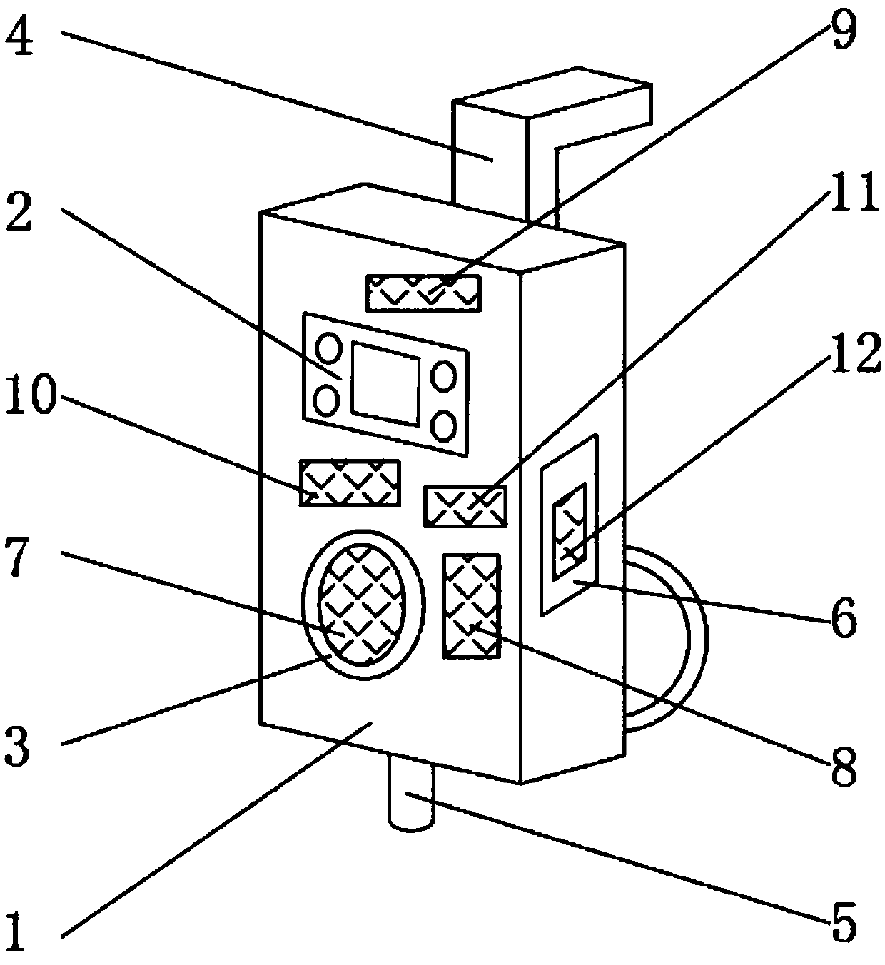
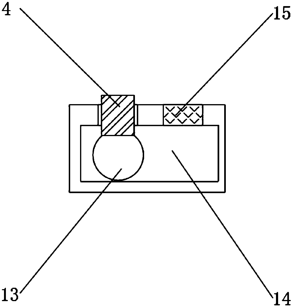
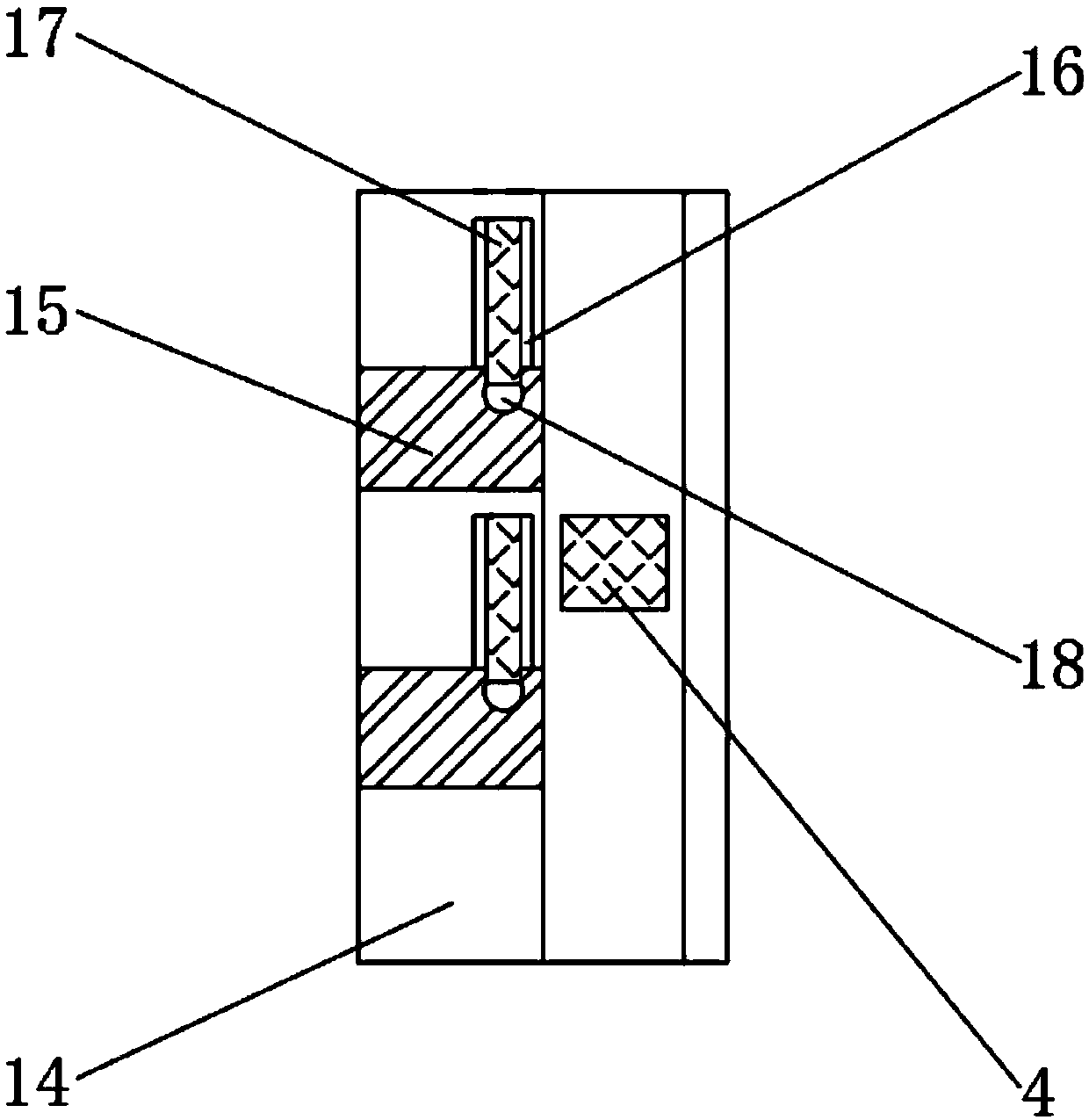
Novel electric cabinet dehumidifying device easy to install

A technology for electric cabinets and equipment, applied in the field of new electric cabinet dehumidification equipment, can solve the problems of water leakage, fixed installation position, inconvenient disassembly and maintenance for users, and achieve the effects of reducing maintenance costs, optimizing the use process, and increasing safety

Inactive Publication Date: 2019-04-26
江苏成华能源化工设备有限公司
View PDF0 Cites 0 Cited by
  • Summary
  • Abstract
  • Description
  • Claims
  • Application Information

AI Technical Summary

Problems solved by technology

[0002] Dehumidification equipment, as the preferred equipment to remove the moisture inside the object, is a common auxiliary equipment for object maintenance in daily life, but the installation of the existing electric cabinet dehumidification equipment is more troublesome, and the installation position is relatively fixed. It is not convenient for users to disassemble and maintain, and the fixed installation position affects the dehumidification effect of the equipment to a certain extent. In addition, the connection between the drain pipe and the water guide hose is not stable enough, and water is easy to leak from the connection, thereby increasing the dehumidification work of the equipment

Method used


Image

  • Novel electric cabinet dehumidifying device easy to install
  • Novel electric cabinet dehumidifying device easy to install
  • Novel electric cabinet dehumidifying device easy to install

Examples


Embodiment Construction

[0016] The following will clearly and completely describe the technical solutions in the embodiments of the present invention with reference to the accompanying drawings in the embodiments of the present invention. Obviously, the described embodiments are only some, not all, embodiments of the present invention. Based on the embodiments of the present invention, all other embodiments obtained by persons of ordinary skill in the art without making creative efforts belong to the protection scope of the present invention.

[0017] In the description of the present invention, it should be noted that the terms "upper", "lower", "inner", "outer", "front end", "rear end", "both ends", "one end", "another end" The orientation or positional relationship indicated by etc. is based on the orientation or positional relationship shown in the drawings, and is only for the convenience of describing the present invention and simplifying the description, rather than indicating or implying that ...


PUM


Abstract

The invention discloses a novel electric cabinet dehumidifying device easy to install. The dehumidifying device comprises a casing. The outer surface at the front end of the casing is fixedly providedwith an operation panel, an air outlet is arranged below the operation panel, the outer surface at the rear end of the casing is fixedly provided with a connecting rod, and a drain pipe is disposed on the outer surface at the lower end of the casing. A heat dissipation port is disposed in the outer surface at one end of the casing, and a fan is fixedly mounted in the casing at the position closeto an air outlet. A condensation module is fixedly mounted on one side of the fan, and a control module is fixedly mounted above the fan. A heater is fixedly mounted between the fan and the control module, and a temperature and humidity sensor is fixedly mounted on one side of the heater. A heat sink is fixedly mounted inside the casing at the position close to the heat dissipation port. By meansof a series of structures, the dehumidifying device achieves the advantages of safe water guiding, convenient installation and movement during use, and the use process is optimized.

Description

technical field [0001] The invention relates to the field of dehumidification equipment, in particular to a novel electric cabinet dehumidification equipment that is easy to install. Background technique [0002] Dehumidification equipment, as the preferred equipment to remove the moisture inside the object, is a common auxiliary equipment for object maintenance in daily life, but the installation of the existing electric cabinet dehumidification equipment is more troublesome, and the installation position is relatively fixed. It is not convenient for users to disassemble and maintain, and the fixed installation position affects the dehumidification effect of the equipment to a certain extent. In addition, the connection between the drain pipe and the water guide hose is not stable enough, and water is easy to leak from the connection, thereby increasing the dehumidification work of the equipment. Contents of the invention [0003] The purpose of the present invention is t...

Claims


Application Information

Patent Timeline
Patent Type & Authority Applications(China)
IPC IPC(8): H02B1/30H02B1/56
CPCH02B1/30H02B1/565
Inventor 杨少民陈超丁剑鸣
Owner 江苏成华能源化工设备有限公司
Why Eureka
Try Eureka