Novel permanent-magnet magnet-assisted synchronous reluctance motor
A synchronous reluctance motor and permanent magnet technology, applied in the direction of magnetic circuit shape/style/structure, magnetic circuit, electrical components, etc., can solve the problem of reducing the stator current excitation component, difficult to further increase torque density, low motor power factor, etc. problem, to achieve the effect of increasing salient pole difference, increasing torque density, and improving power factor
- Summary
- Abstract
- Description
- Claims
- Application Information
AI Technical Summary
Problems solved by technology
Method used
Image


Examples
Embodiment 1
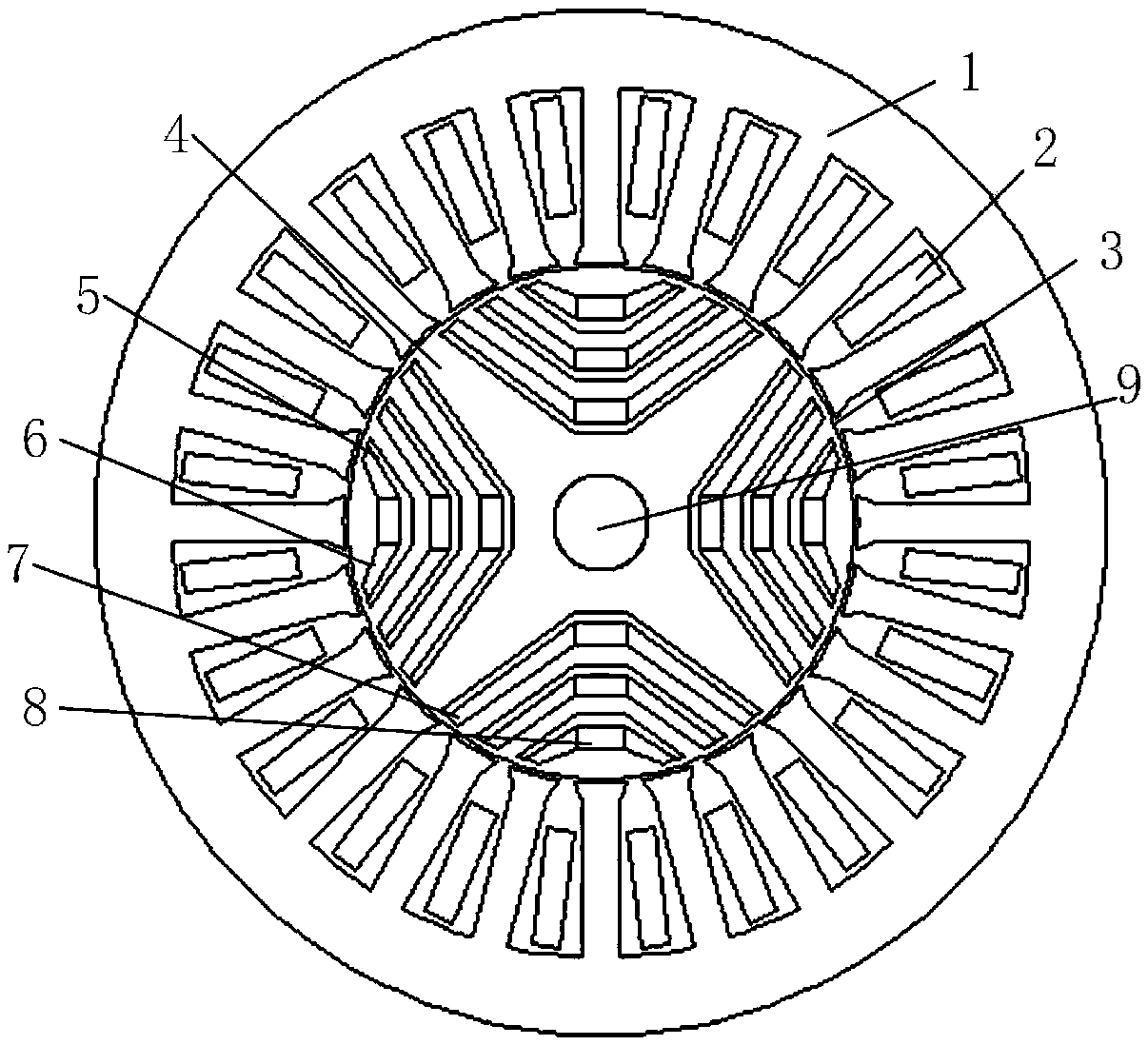
[0031] Such as Figure 1 to 2 As shown in this embodiment, a new type of permanent magnet assisted synchronous reluctance motor includes a stator core 1, a three-phase symmetrical winding 2, an air gap 3 between the stator core and the rotor core, the rotor core 4. Oriented silicon steel sheet 5, N-pole permanent magnet 6, S-pole permanent magnet 7, air or non-magnetic material 8 and rotating shaft 9. The oriented silicon steel sheet 5 has three layers: the oriented silicon steel sheet 51 in the first layer of magnetic barrier, the oriented silicon steel sheet 52 in the second layer of magnetic barrier, and the oriented silicon steel sheet 53 in the third layer of magnetic barrier; The magnet has three layers: N-pole permanent magnet 61 in the first layer of magnetic barrier, N-pole permanent magnet 62 in the second layer of magnetic barrier, and N-pole permanent magnet 63 in the third layer of magnetic barrier; air or non-magnetic material 8 There are three layers: air or non...
Embodiment 2
[0037] The structure of the new type permanent magnet assisted synchronous reluctance motor of this embodiment is the same as that of Embodiment 1, except that the number of barrier layers in this embodiment is two. image 3 Shown is the specific structure diagram of the two-layer magnetic barrier rotor iron core of the novel permanent magnet-assisted synchronous reluctance motor of the present invention; including the rotor iron core 4, the oriented silicon steel sheet 51 in the first layer of magnetic barrier, and the second layer of magnetic Oriented silicon steel sheet 52 in the barrier; N-pole permanent magnet 61 in the first layer of magnetic barrier, N-pole permanent magnet 62 in the second layer of magnetic barrier; Air or non-magnetic material 81 in the first layer of magnetic barrier; Air or non-magnetic material 82 in the second layer of magnetic barrier. In each layer of the magnetic barrier, the length of the oriented silicon steel sheet is the same as the length of...
PUM
 Abstract
Description
Claims
Application Information
 - R&D
- Intellectual Property
- Life Sciences
- Materials
- Tech Scout
- Unparalleled Data Quality
- Higher Quality Content
- 60% Fewer Hallucinations
Browse by: Latest US Patents, China's latest patents, Technical Efficacy Thesaurus, Application Domain, Technology Topic, Popular Technical Reports.
© 2025 PatSnap. All rights reserved.Legal|Privacy policy|Modern Slavery Act Transparency Statement|Sitemap|About US| Contact US: help@patsnap.com