Orientation silicon steel sheet rotor core and synchronous reluctance motor

A technology of synchronous reluctance motors and oriented silicon steel, which is applied in the direction of motors, electric components, electric vehicles, etc., can solve the problems of increasing the salient pole difference of synchronous reluctance motors, complex magnetic barrier shapes, and difficult manufacturing, and achieve reluctance Reduced size, convenient production and processing, avoiding the effect that is not easy to make

Pending Publication Date: 2022-08-09
HEBEI UNIV OF TECH
View PDF0 Cites 0 Cited by
  • Summary
  • Abstract
  • Description
  • Claims
  • Application Information

AI Technical Summary

Problems solved by technology

[0004] The object of the present invention is to propose a kind of oriented silicon steel sheet rotor iron core and synchronous reluctance motor, to solve the technical problems existing in the above-mentioned background technology, apply oriented silicon steel sheet material to improve the magnetic permeability of the d-axis magnetic field of synchronous reluctance motor, improve Output torque; In order to solve the problem of difficult manufacturing when the shape of the magnetic barrier is complex and the number of layers of the magnetic barrier is large in the traditional integrated rotor core, the motor rotor core of the method is composed of a plurality of oriented silicon steel sheet components with the same structure Assembled, it is convenient for large-scale processing and manufacturing, and the rolling direction of each grain-oriented silicon steel sheet assembly is parallel to the d-axis of the rotor core. Taking advantage of the characteristics of good magnetic conductivity and high magnetic permeability in the rolling direction of grain-oriented silicon steel sheets, it is effective Increase the salient pole difference of the synchronous reluctance motor, thereby increasing its output torque

Method used


Image

  • Orientation silicon steel sheet rotor core and synchronous reluctance motor
  • Orientation silicon steel sheet rotor core and synchronous reluctance motor
  • Orientation silicon steel sheet rotor core and synchronous reluctance motor

Examples


Embodiment 1

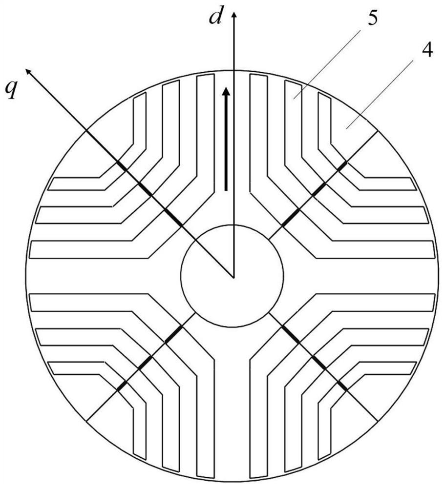
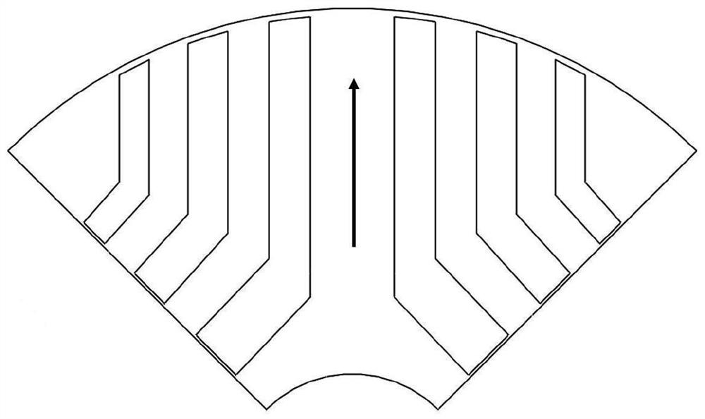
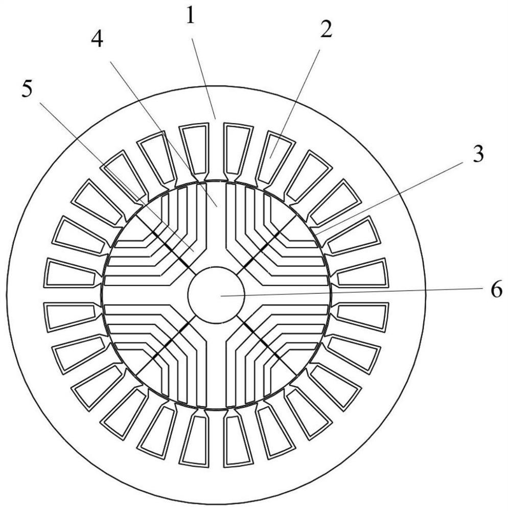
[0028] This embodiment provides an oriented silicon steel sheet rotor core (see Figure 1-2 ), characterized in that the rotor core is a hollow cylindrical structure assembled and bonded by four oriented silicon steel sheet components with the same structure and the same rolling direction, and the through hole at the center of the cylindrical structure is the motor shaft mounting hole; Each oriented silicon steel sheet assembly is formed by a plurality of identical oriented silicon steel sheets 4 aligned and laminated along the axial direction of the motor shaft, and two adjacent oriented silicon steel sheets 4 are fixed together by bonding. The rolling directions of the grain-oriented silicon steel sheets 4 are all the same.

[0029] The rolling direction of the oriented silicon steel sheet 4 is consistent with the d-axis direction of the rotor core, that is, the low reluctance direction at the location where it is installed. And two sets of magnetic barrier structures 5 are...


PUM


Abstract

The invention discloses an oriented silicon steel sheet rotor core and a synchronous reluctance motor, the rotor core is formed by splicing a plurality of oriented silicon steel sheet assemblies with the same structure, the rolling direction of an oriented silicon steel sheet in each assembly is parallel to the d axis of the rotor core, and the advantage that the oriented silicon steel sheet is high in magnetic conductivity in the rolling direction is fully exerted; the magnetic resistance of the d axis is reduced, the inductance is increased, the salient pole difference and the salient pole rate of the synchronous reluctance motor are further improved, the torque density and the power factor of the motor are improved, and beneficial exploration is provided for research of the synchronous reluctance motor. Besides, the synchronous reluctance motor is convenient to produce and process, and for the rotor core with complex magnetic barrier shapes and more magnetic barrier layers, only the oriented silicon steel sheets need to be pressed into a plurality of oriented silicon steel sheet assemblies with the same structure, and the oriented silicon steel sheet assemblies are combined and assembled after being pressed, so that the problem that the integrated rotor core is not easy to manufacture is avoided.

Description

technical field [0001] The invention belongs to the technical field of synchronous reluctance motors, in particular to an oriented silicon steel sheet rotor core and a synchronous reluctance motor. Background technique [0002] In recent years, due to the gradual decrease in the reserves of high-performance rare earth permanent magnet materials and the rising prices, the demand for motors with higher performance and lower cost is growing rapidly. Research on electromagnetic devices with less rare earth permanent magnet materials such as reluctance motors become more and more important. Among them, the synchronous reluctance motor can operate without permanent magnet excitation, but follows the principle of minimum reluctance, and generates reluctance torque by using the inductance difference between the d-axis and the q-axis. Due to its advantages of low price, simple processing, reliable structure and wide range of speed regulation, it is widely used in compressors, househ...

Claims


Application Information

Patent Timeline
Patent Type & Authority Applications(China)
IPC IPC(8): H02K1/22H02K1/28H02K3/28H02K3/12H02K3/52
CPCH02K1/22H02K1/28H02K3/28H02K3/12H02K3/522H02K2213/03Y02T10/64
Inventor 刘成成张世伟汪友华
Owner HEBEI UNIV OF TECH
Why Eureka
Try Eureka