Rotor assembly and self-starting permanent magnet synchronous reluctance motor

A technology of components and rotors, applied in synchronous machine parts, electric components, magnetic circuit rotating parts, etc., can solve the problems of reducing magnetic flux, complicated control, and high cost

Active Publication Date: 2021-06-15
GREE ELECTRIC APPLIANCES INC
View PDF14 Cites 0 Cited by
  • Summary
  • Abstract
  • Description
  • Claims
  • Application Information

AI Technical Summary

Problems solved by technology

[0003] Traditional permanent magnet motors and self-starting permanent magnet synchronous reluctance motors require a driver to start and control the operation, which is costly and complicated to control, and the driver occupies a part of the loss, which reduces the efficiency of the entire motor system
[0004] The Chinese invention patent with the patent publication number CN107994698A provides a self-starting permanent magnet synchronous reluctance motor to reduce the cost of permanent magnets. However, in this patent, the magnetic flux concentrates along the direction of the q-axis, which reduces the magnetic flux in the direction of the d-axis. Reduced magnetic torque and reduced motor performance

Method used


Image

  • Rotor assembly and self-starting permanent magnet synchronous reluctance motor
  • Rotor assembly and self-starting permanent magnet synchronous reluctance motor
  • Rotor assembly and self-starting permanent magnet synchronous reluctance motor

Examples


Embodiment Construction

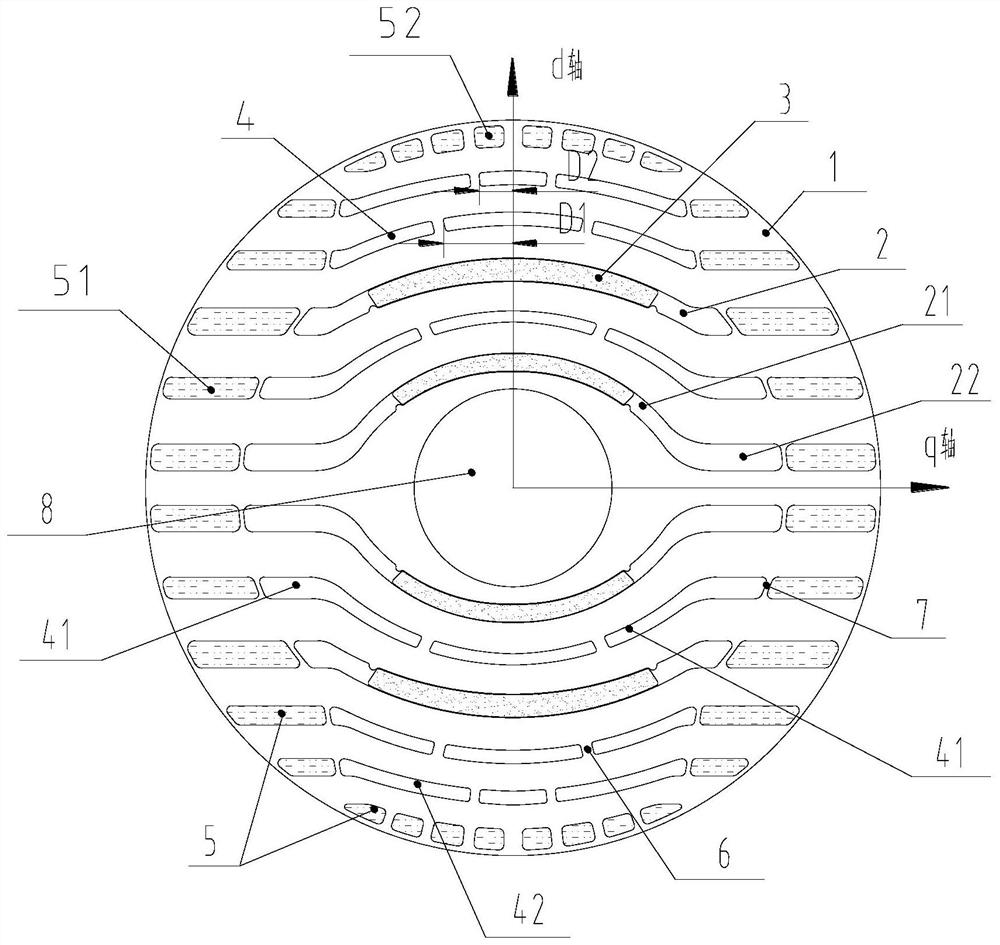
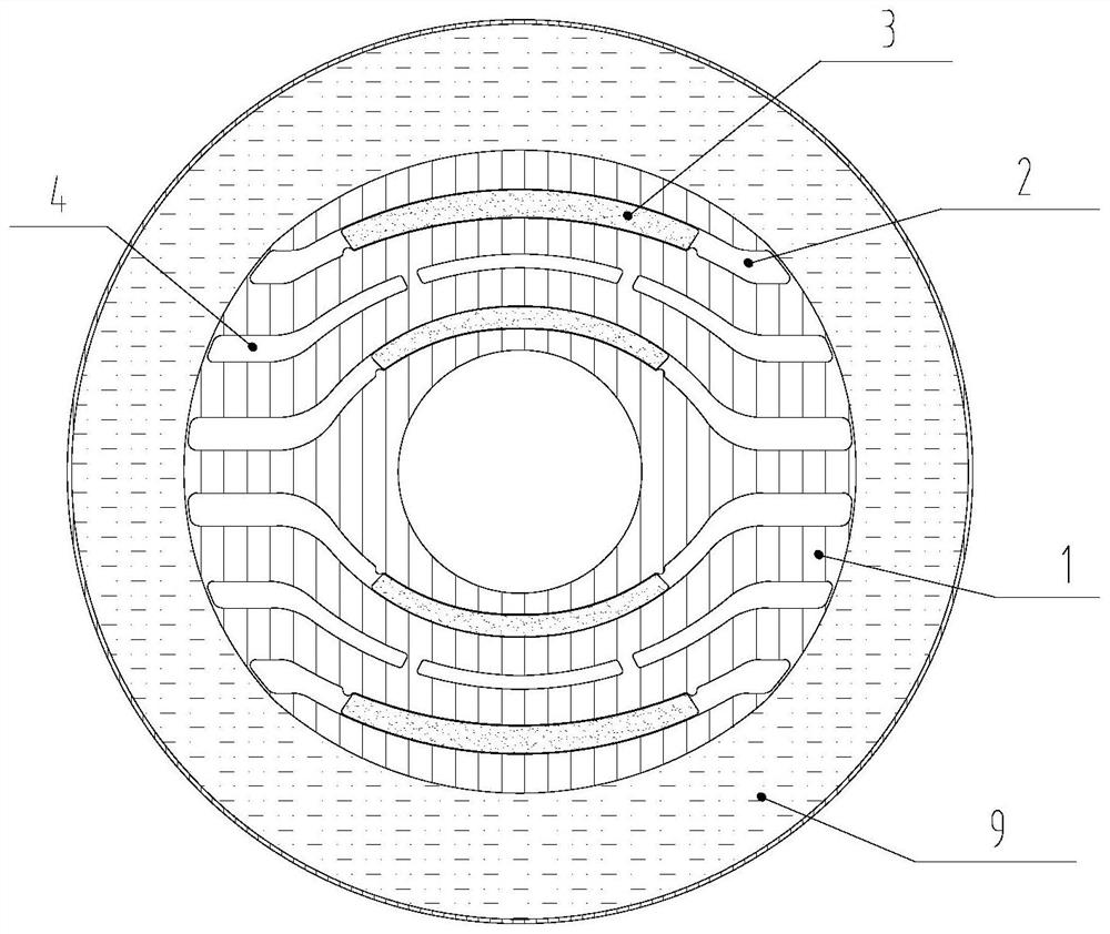
[0034] see in conjunction Figure 1 to Figure 3 As shown, according to the embodiment of the present application, the rotor assembly includes a rotor core 1. On the cross section of the rotor core 1, the rotor core 1 is provided with a shaft hole 8, a mounting slot 2, a magnetic barrier slot 4 and a plurality of rats. The cage slots 5, the installation slots 2 are arranged at least two layers along the radial direction of the rotor core 1, the magnetic barrier slots 4 are arranged at least two layers along the radial direction of the rotor core 1, and the squirrel cage slots 5 are distributed on the outer periphery of the rotor core 1, A permanent magnet 3 is installed in the installation groove 2, and the magnetic barrier groove 4 includes an inner layer magnetic barrier groove 41, and the inner layer magnetic barrier groove 41 is located at the radial inner side of the outermost layer installation groove 2, under the same pole, the adjacent installation groove 2 There is at ...


PUM


Abstract

The invention provides a rotor assembly and a self-starting permanent magnet synchronous reluctance motor. The rotor assembly comprises a rotor core (1), the rotor core (1) is provided with mounting grooves (2), magnetic barrier grooves (4) and a plurality of squirrel cage grooves (5) on the cross section of the rotor core (1), permanent magnets (3) are mounted in the mounting grooves (2), the magnetic barrier grooves (4) comprise inner-layer magnetic barrier grooves (41), at least one layer of inner-layer magnetic barrier grooves (41) exists between the adjacent mounting grooves (2) under the same pole, and the squirrel cage grooves (5) are formed in the rotor core (1). At least two first magnetic bridges (6) are arranged on the inner-layer magnetic barrier grooves (41), the width of each first magnetic bridge (6) is C1, the minimum width of a magnetic conduction channel between the inner-layer magnetic barrier groove (41) where the first magnetic bridges (6) are located and the adjacent mounting groove (2) on the radial inner side is C4, and C1 is smaller than 0.5 * C4. According to the rotor assembly, the reluctance torque and the permanent magnet torque of the motor can be increased at the same time, and the performance and efficiency of the motor are improved.

Description

technical field [0001] The present application relates to the technical field of motors, in particular to a rotor assembly and a self-starting permanent magnet synchronous reluctance motor. Background technique [0002] The self-starting permanent magnet synchronous reluctance motor combines the structural characteristics of the induction motor and the synchronous permanent magnet reluctance motor. The starting torque is generated by the squirrel cage induction, and the constant torque is realized by the difference between the d and q axis magnetic flux of the rotor and the torque generated by the permanent magnet. It can run at high speed and can be directly connected to the power supply to realize the starting operation. The self-starting permanent magnet synchronous reluctance motor can use the reluctance torque to increase the output torque of the motor. Compared with the self-starting permanent magnet motor, the amount of permanent magnets is reduced and the cost is red...

Claims


Application Information

Patent Timeline
Patent Type & Authority Applications(China)
IPC IPC(8): H02K1/27H02K21/02
CPCH02K1/27H02K1/272H02K21/02H02K2213/03
Inventor 肖勇陈彬史进飞张志东李霞
Owner GREE ELECTRIC APPLIANCES INC
Why Eureka
Try Eureka