Laminating and conveying device of paper mounting machine

A technology for conveying devices and laminating machines, which is applied in lamination devices, lamination, transportation and packaging, etc. It can solve problems affecting paper transmission efficiency, limited use of laminating machine equipment, and failure of normal transmission of pasted paper, etc., to achieve Ensuring operational efficiency and expanding the scope of application

Pending Publication Date: 2019-04-30
郭福明
View PDF8 Cites 0 Cited by
  • Summary
  • Abstract
  • Description
  • Claims
  • Application Information

AI Technical Summary

Problems solved by technology

[0003] Those skilled in the art have analyzed the deficiencies of the known technology of the existing paper laminating machine. Since the conveying mechanism of the paper laminating machine is generally used to transmit the paper separately for glue coating and pasting, when pasting, sometimes more or less paper needs to be pasted. , the thickness of the paper on the conveyor belt of the pasting and laminating mechanism also increases or decreases accordingly, and different quantities of paper have different transmission requirements after pasting. The corresponding conveying device is set at the paper output position and waits, so that the pasted paper after gluing and pasting directly enters the next conveying device for conveyance. Since the thickness of the paper will change during the pasting process, if the glued and pasted thick paper or the thickness of the stacked paper is high , the thickness of the stacked paper at the piled paper is different, and the formed height is also different. When the thickness is large, the pasting press mechanism cannot automatically adjust the horizontal height between the next conveying device that is docked, so that the pasted paper after glued and pasted It cannot be transferred to the next conveying device normally, which will not only affect the quantity and efficiency of the laminating and pasting of the conveying and laminating device, but also affect the subsequent conveying efficiency of the pasted paper
[0004] Therefore, in the past, the transfer of pasting papers of different thicknesses stacked at the stacking position was mostly carried out manually. Obviously, the prior art has not yet found the next transfer device that can be adjusted by itself for docking with the pasting pressing mechanism, which eventually leads to Laminator equipment is limited, affecting the ability to laminate different quantities of paper

Method used


Image

  • Laminating and conveying device of paper mounting machine
  • Laminating and conveying device of paper mounting machine
  • Laminating and conveying device of paper mounting machine

Examples


Embodiment 1

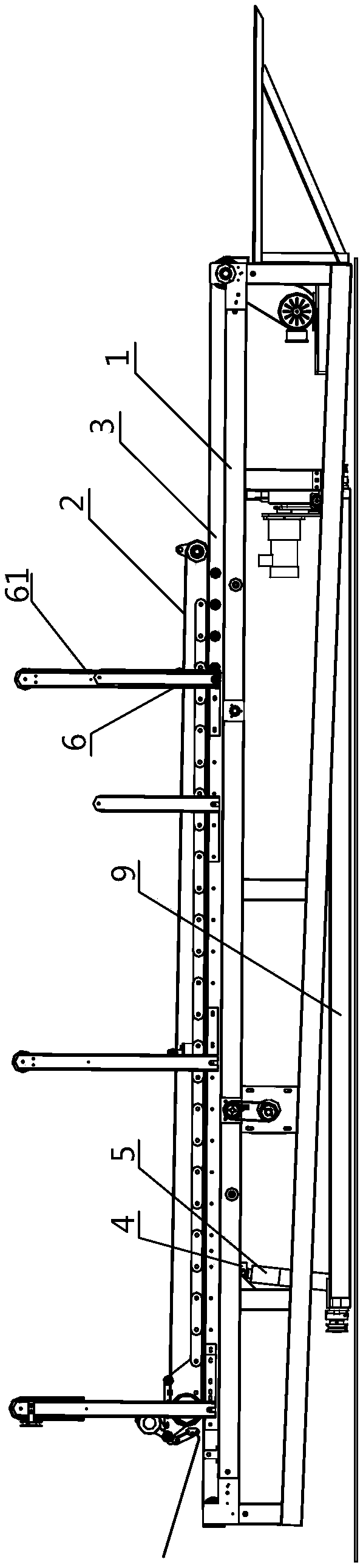
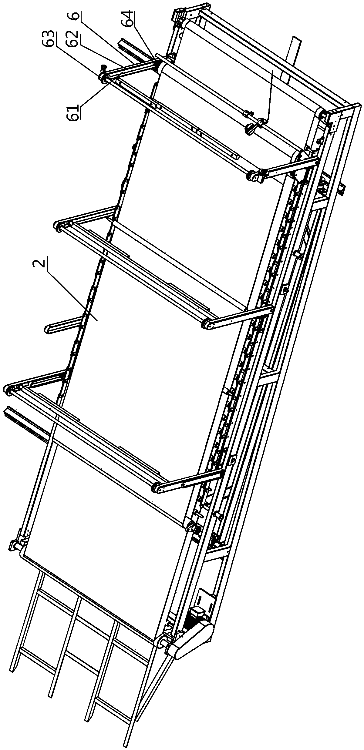
[0038] Such as Figure 1-4 As shown, the purpose of the technical means implemented in the pressing and conveying device of the laminating machine described in Embodiment 1 of the present invention is to solve the problem of the traditional laminating machine equipment transferring two sheets of paper separately through the conveying mechanism for gluing and pasting. Afterwards, because of the inability to automatically adjust the level between the next conveying device that is docked, the pasted paper after gluing and pasting cannot be conveyed normally. The frame body 1 that lowers the conveyor belt and transports the paper separately.

[0039] For the analysis of the rack body 1 structure with the above settings:

[0040] One end of the implemented frame body 1 is set as a paper feed end, and correspondingly, the other end is set as a paper output end, and the implemented lower conveyor belt 3 is fixedly arranged on the upper surface of the frame body 1, and the implemente...

Embodiment 2

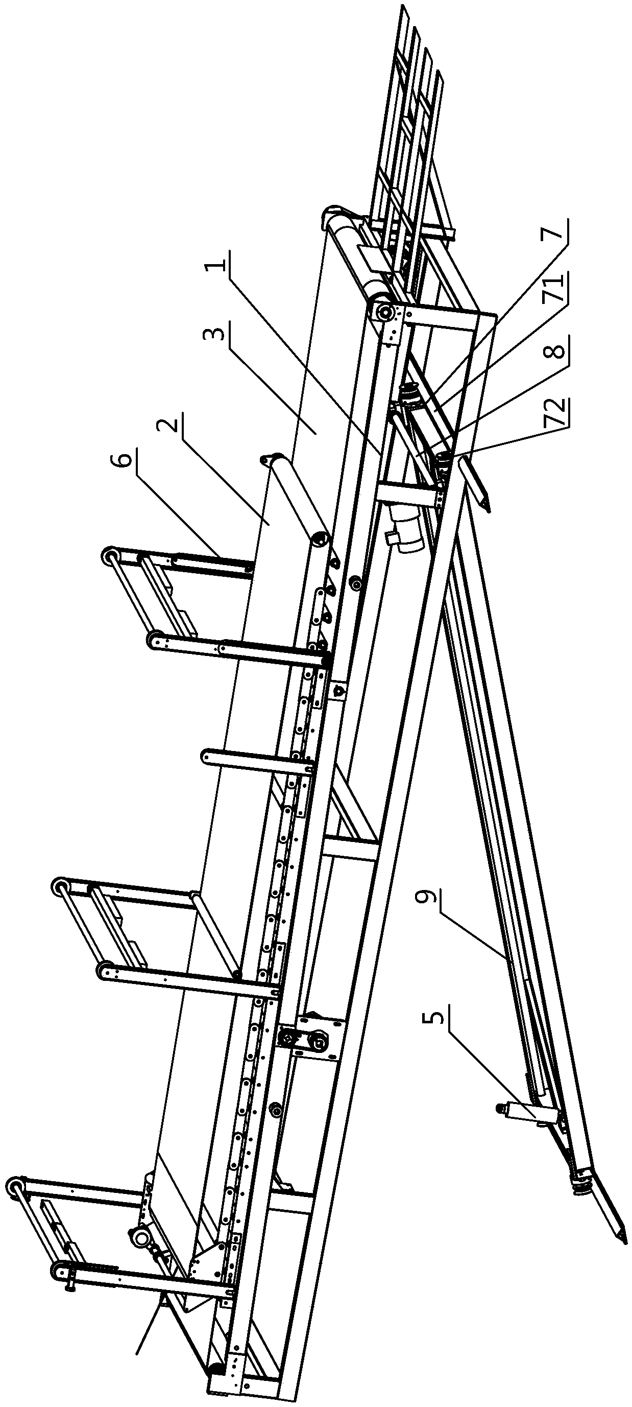
[0047] Such as Figure 1-4 As shown, the technical means implemented in the pressing and conveying device of the laminating machine described in the second embodiment of the present invention are further supplements on the basis of the technical solution implemented in the first embodiment, and belong to the technical solution adopted in the first embodiment. The same idea and the same technical problem are solved. The specific implementation means are that the two ends of the implemented support frame 9 are provided with some guide wheels 72, and the guide wheels 72 at the same end are arranged on the corresponding wheel rail 71 and can be positioned on the wheel rail 71. Sliding on the top, the two ends of the implemented wheel rail 71 are fixed on the bottom beam of the frame body 1. Since the hydraulic cylinder 5 of the support frame 9 is connected with the fixed connector 4 at the bottom of the lower conveyor belt 3, when the motor drives the guide wheel 72 When sliding o...


PUM


Abstract

The invention relates to a laminating and conveying device of a paper mounting machine, the laminating and conveying device comprises an upper-layer adjustable conveying unit, a lower-layer adjustableconveying unit and a supporting frame, wherein the upper-layer adjustable conveying unit is arranged above a lower conveying belt, and comprises a vertical lifting mechanism for adjusting the horizontal height of an upper conveying belt, the lower-layer adjustable conveying unit is arranged below the lower conveying belt, and comprises a hydraulic lifting mechanism for adjusting the distance between the upper conveying belt and the lower conveying belt, and the supporting frame is arranged at the bottom of the hydraulic lifting mechanism. A hydraulic lifting unit is adopted to drive a deviceplatform to move upwards or downwards, so that the relative horizontal position between the paper discharging position of a gluing and pasting mechanism and the device platform can be met, and the running efficiency of the paper mounting machine can be ensured; when the thickness of pasting paper between the upper conveying belt and the lower conveying belt is increased or decreased, by adjustmentthrough the upper conveying belt and the lower conveying belt, different numbers of the pasting paper can be conveyed and compacted.

Description

technical field [0001] The invention relates to the field of paper production machinery and equipment, in particular to a pressing and conveying device for a laminating machine. Background technique [0002] Laminating machine is a kind of paper processing equipment used to paste two pieces of paper together. In the specific production process, paper laminating machine is often used to laminate cardboard with colorful patterns and corrugated paper together to replace Manual lamination of top paper and bottom paper has the advantages of fast processing efficiency and accurate alignment of top and bottom paper. Its structure generally includes a frame, and a paper feeding mechanism, a gluing mechanism, a pressing mechanism, a paper feeding mechanism, etc. arranged on the frame. When the paper laminating machine is working, there is a conveyor belt on the paper feeding mechanism, and the conveyor belt reciprocates around the paper feeding machine to transport the surface paper...

Claims


Application Information

Patent Timeline
Patent Type & Authority Applications(China)
IPC IPC(8): B32B37/12B32B37/10B65H5/02
CPCB65H5/023B32B37/10B32B37/12B65H2404/2615
Inventor 苏仕胜郭福明
Owner 郭福明
Why Eureka
Try Eureka