
Iron shoe monitoring method and device and iron shoe thereof

An iron shoe and orientation technology, which is applied in the field of the device and its iron shoe, and the iron shoe monitoring method, can solve the problems of insufficient comprehensive monitoring and information security, and cannot monitor the safety of the iron shoe, and achieves difficult management, strong penetration ability, good stability

Pending Publication Date: 2019-04-30
湖南铭桥信息科技有限公司 +1
View PDF6 Cites 3 Cited by
  • Summary
  • Abstract
  • Description
  • Claims
  • Application Information

AI Technical Summary

Problems solved by technology

[0003] In recent years, traditional iron shoes have gradually become intelligent, but there are still deficiencies in comprehensive monitoring and information security, and it is not possible to conduct comprehensive security monitoring on iron shoes stably

Method used


Image

  • Iron shoe monitoring method and device and iron shoe thereof
  • Iron shoe monitoring method and device and iron shoe thereof
  • Iron shoe monitoring method and device and iron shoe thereof

Examples


Embodiment 1

[0069] See Figure 4 , the iron shoe monitoring device includes a detection module 31, a control module 32 and a wireless positioning communication module 33, wherein: the detection module 31 is used to obtain the state parameters of the iron shoes; the wireless positioning communication module 33 is used to obtain the iron shoe positioning parameters; the control module 32 is used to compare the obtained state parameters and positioning parameters with corresponding preset parameter thresholds to obtain corresponding comparison results; the control module 32 is also used to Controlling the wireless positioning communication module 33 to send the acquired state parameters, the positioning parameters, and the comparison results to the upper computer through carrierless communication. Wherein, the detection module 31 and the wireless positioning communication module 33 are respectively electrically connected to the control module 32, and the control module 32 is also used to con...

Embodiment 2

[0076] This embodiment is an iron shoe structure provided according to the solution of the present invention, please refer to Figure 14 and Figure 15 , is a schematic diagram of the structure of the iron shoe before and after assembly. The iron shoe includes an iron shoe body 51 and a control box 52. The iron shoe body 51 includes a base 54 and a housing 53. The housing 53 includes a top plate 55 and a vertical plate 56 arranged around the top plate 55. The vertical plate 56 is connected to the top plate 55 and the base. 54, the base 54, the vertical plate 56 and the top plate 55 jointly form an open chamber 50, and the control box 52 is accommodated in the chamber 50. The control box 52 includes a detection module and a control module 32 electrically connected to the detection module. A first through hole 111 is provided on the iron shoe body 51 at a position corresponding to the detection module. In this embodiment, the material of the control box 52 is nylon material, w...


PUM


Abstract

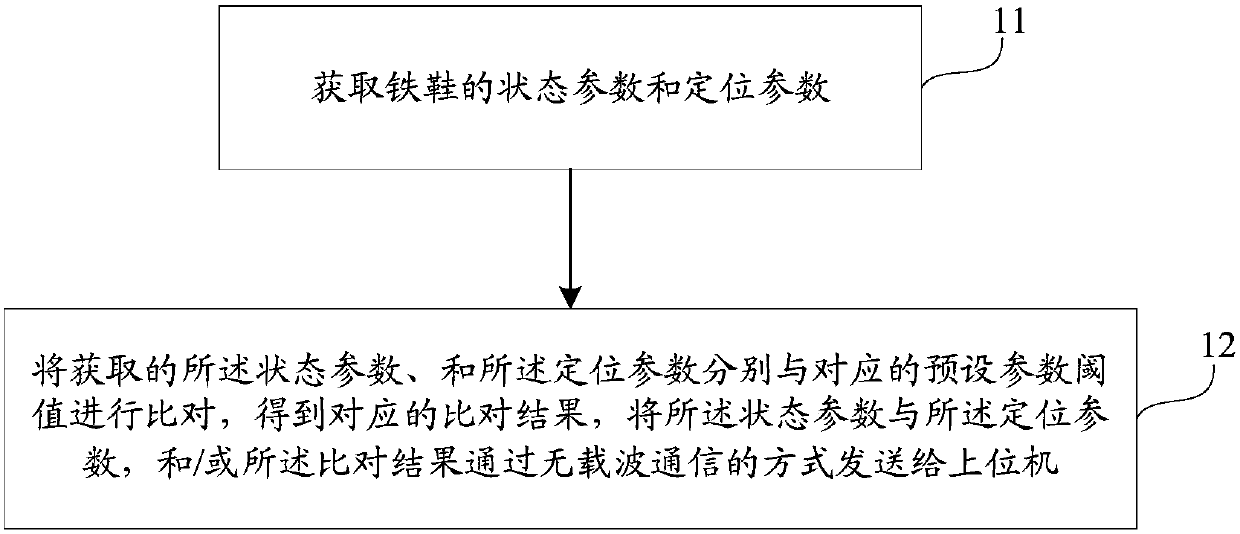
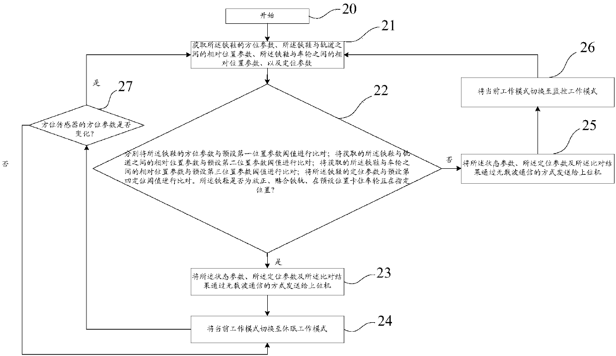
The embodiment of the invention discloses an iron shoe monitoring method. The method comprises the following steps of obtaining state parameters and positioning parameters of an iron shoe; and comparing the acquired state parameters and positioning parameters with corresponding preset parameter thresholds respectively to obtain corresponding comparison results, and sending the state parameters, the positioning parameters and / or the comparison results to an upper computer in a carrier-free communication manner. The embodiment of the invention further discloses an iron shoe monitoring device andan iron shoe. The state information of the iron shoe is comprehensively acquired and is sent to the upper computer in a carrier-free communication mode, so that the iron shoe can be stably and safelymonitored comprehensively.

Description

technical field [0001] The invention relates to the field of vehicle braking, in particular to a shoe monitoring method and device in locomotives and the shoe. Background technique [0002] In the rail transit system, if a locomotive that stops running slips, it will lead to serious consequences. Therefore, effective technical measures must be taken to prevent such accidents, especially with the rapid development of rail transit in recent years, parking of locomotives Safety puts forward higher requirements. As the main tool of intelligence when the locomotive stops, the iron shoes are placed on the wheels on both sides of the locomotive. The special structure of the iron shoes can effectively prevent the wheels from sliding and prevent the locomotive from rolling. It plays a role when the train stops running. extremely important role. [0003] In recent years, traditional iron shoes have gradually become intelligent, but there are still deficiencies in comprehensive monit...

Claims


Application Information

Patent Timeline
IPC IPC(8): B61H7/02B61L23/00G01S15/06
Inventor 荣航铭王亚敏王吉桥丁代劲闫柏辉师少敏黄坚
Owner 湖南铭桥信息科技有限公司
Learn More