Glass placing rack

A technology for placing racks and glass, applied to conveyor objects, furnaces, lighting and heating equipment, etc., can solve problems such as easy shaking, insufficient mechanical lifting force, hidden safety hazards, etc., to reduce safety hazards and prevent glass from causing damage. Effect

Inactive Publication Date: 2019-04-30
北京中建润通机电工程有限公司
View PDF8 Cites 16 Cited by
  • Summary
  • Abstract
  • Description
  • Claims
  • Application Information

AI Technical Summary

Problems solved by technology

[0004] The structure of this glass rack is simple, but there is a problem in actual use. When installing glass, the lower floors are transported manually, while the higher floors are transported by electric hoists or tower cranes. When the glass rack is transported into the air, it will be blown by the wind. At the same time, the mechanical lifting force of the electric hoist or tower crane is not stable enough, and the steel wire rope is relatively soft. Various reasons cause the glass rack to shake easily when it is in the air. If it is too large, the glass will rotate in a direction away from the vertical bar with its lower edge as the rotating shaft, and then fall from the glass shelf, which poses a safety hazard

Method used


Image

  • Glass placing rack
  • Glass placing rack
  • Glass placing rack

Examples


Embodiment

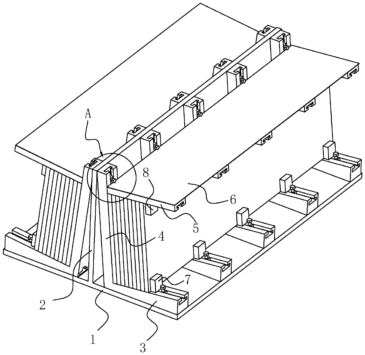
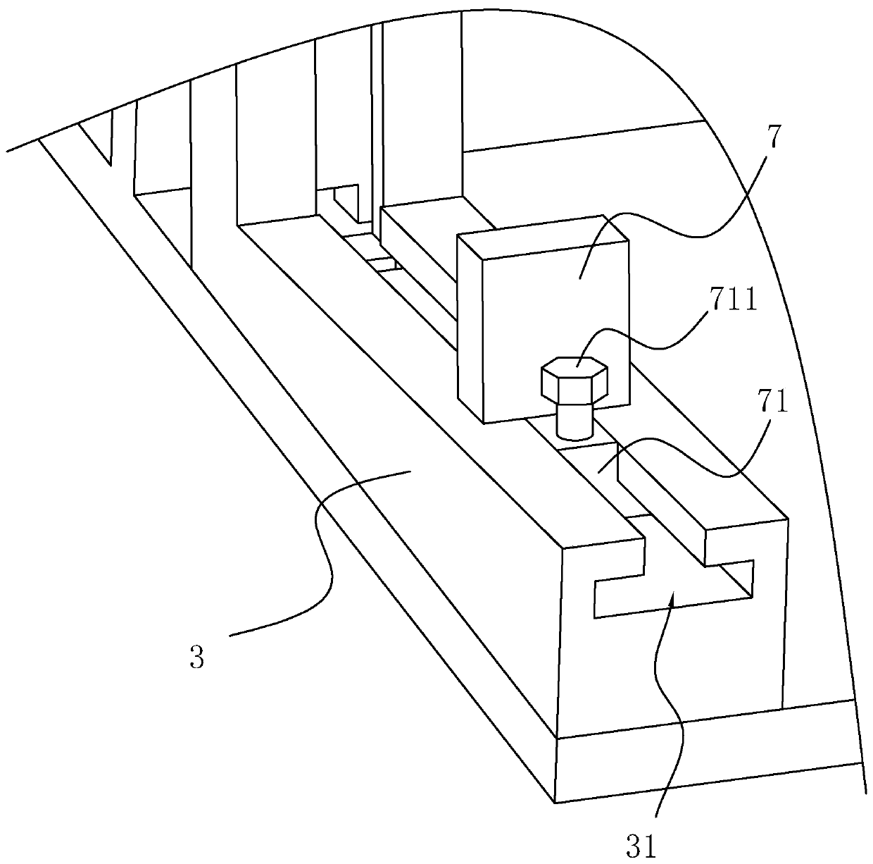
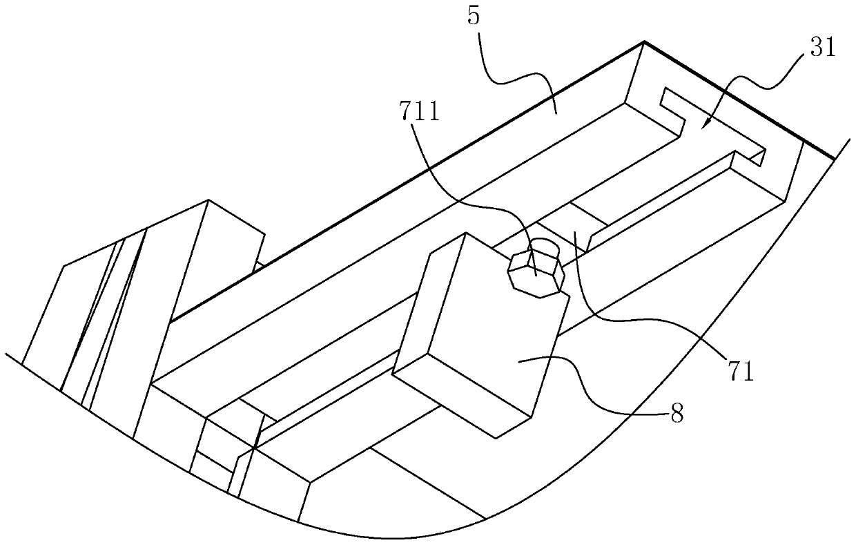
[0031] Embodiment: a kind of glass placement rack, see attached figure 1 , including a bottom plate 1 arranged horizontally, a vertical riser 2 fixedly connected to the top of the bottom plate 1 and located in the middle of the width direction of the bottom plate 1, a number of support rods 3 fixedly connected to the top of the bottom plate 1 and located on both sides of the riser 2 1. The relying rod 4 fixedly connected to the top of the support rod 3 near the end of the vertical plate 2, the cross bar 5 fixedly connected to the side of the supporting rod 4 away from the vertical plate 2, the top limit block 8 arranged on the bottom side of the cross bar 5, The bottom limit block 7 arranged on one side of the top of the support rod 3 and the two shielding plates 6 arranged above the bottom plate 1 and on both sides of the vertical plate 2 . The two ends of the riser 2 are respectively flush with the two ends of the base plate 1; the length direction of the support rods 3 is p...


PUM


Abstract

The invention discloses a glass placing rack, and relates to the technical field of glass transportation. The problem that an existing glass placing rack has safety hazards during transportation of glass is solved. According to key points of the technical scheme, the glass placing rack comprises a bottom plate, a vertical plate, a plurality of supporting rods, reclining rods, transverse rods, toppart limiting blocks, and bottom part limiting blocks, wherein the vertical plate is fixedly connected to the top of the bottom plate, the supporting rods are fixedly connected to the top of the bottom plate, the reclining rods are fixedly connected to the ends, near the vertical plate, of the supporting rods, the transverse rods are arranged on the sides, deviating from the vertical plate, of thereclining rods, the top part limiting blocks are arranged on the bottom parts of the transverse rods, and the bottom part limiting blocks are arranged on the top parts of the supporting rods and canslide on the top parts of the supporting rods in the length direction of the supporting rods. A glass is abutted against the reclining rods by the top part limiting blocks and the bottom part limitingblocks, so that the glass does not rotate when the glass placing rack shakes, thus the glass does not fall off from the glass placing rack, andthe safety hazard is reduced.

Description

technical field [0001] The invention relates to the technical field of glass transportation, more specifically, it relates to a glass placement rack. Background technique [0002] In the housing construction project, after the building frame is built, the glass needs to be installed. The glass is transported to the construction site by a transport vehicle, and is pre-stored on the glass rack after unloading. [0003] The Chinese utility model patent document with the authorized announcement number CN204280348U discloses a glass placement rack, including a push rod, a first basic rod and a second basic rod, the first basic rod and the second basic rod are parallel to each other, so The ejector rod is located above the first basic rod and the second basic rod, and four parallel connecting rods are arranged between the first basic rod and the second basic rod to connect the first basic rod and the second basic rod. The basic rods are connected, and a vertical rod is arranged b...

Claims


Application Information

Patent Timeline
Patent Type & Authority Applications(China)
IPC IPC(8): B65G49/06
CPCB65G49/062
Inventor 聂昌龙
Owner 北京中建润通机电工程有限公司
Why Eureka
Try Eureka