Environmentally friendly U-shaped ring with high strength
A high-strength, U-shaped technology, applied in the field of U-shaped rings, can solve problems such as unfavorable operations, increase the working intensity of tower operators, and complicated operations, so as to achieve the effect of convenient locking and closing and improving anti-oxidation performance
- Summary
- Abstract
- Description
- Claims
- Application Information
AI Technical Summary
Problems solved by technology
Method used
Image

Examples
Embodiment 1
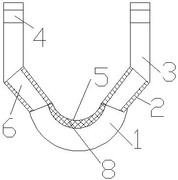
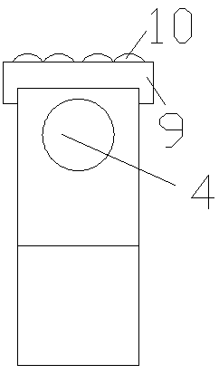
[0014] An environmentally friendly high-strength U-shaped ring is provided with a bottom ring 1, a guide rod 2 is arranged on the bottom ring 1, a connecting rod 3 is arranged on the upper end of the guide rod 2, and a connecting rod 3 is arranged on the upper end of the connecting rod 3 is provided with a connection hole 4, and an anti-oxidation component 5 is provided inside the bottom ring 1, and the anti-oxidation component 5 is set on the outside of the bottom ring 1.
[0015] A reinforcement rod 6 is arranged inside the guide rod 2, and the reinforcement rod 6 is a copper rod.
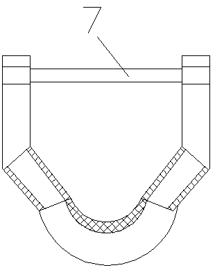
[0016] A limiting component 7 is arranged between the connecting rods 3, and the limiting component 7 is a limiting rod.
[0017] The anti-oxidation component 5 is an anti-oxidation copper sleeve, and an antioxidant coating 8 is coated on the copper sleeve.
Embodiment 2
[0019] An environmentally friendly high-strength U-shaped ring is provided with a bottom ring 1, a guide rod 2 is arranged on the bottom ring 1, a connecting rod 3 is arranged on the upper end of the guide rod 2, and a connecting rod 3 is arranged on the upper end of the connecting rod 3 is provided with a connection hole 4, and an anti-oxidation component 5 is provided inside the bottom ring 1, and the anti-oxidation component 5 is set on the outside of the bottom ring 1.
[0020] A reinforcement rod 6 is arranged inside the guide rod 2, and the reinforcement rod 6 is a copper rod.
[0021] A limiting component 7 is arranged between the connecting rods 3, and the limiting component 7 is a limiting rod.
[0022] The anti-oxidation component 5 is an anti-oxidation copper sleeve, and an antioxidant coating 8 is coated on the copper sleeve.
[0023] The upper end of the connecting rod 3 is provided with a protective cover 9, and the protective cover 9 is directly sleeved on the ...
Embodiment 3
[0025] An environmentally friendly high-strength U-shaped ring is provided with a bottom ring 1, a guide rod 2 is arranged on the bottom ring 1, a connecting rod 3 is arranged on the upper end of the guide rod 2, and a connecting rod 3 is arranged on the upper end of the connecting rod 3 is provided with a connection hole 4, and an anti-oxidation component 5 is provided inside the bottom ring 1, and the anti-oxidation component 5 is set on the outside of the bottom ring 1.
[0026] A reinforcement rod 6 is arranged inside the guide rod 2, and the reinforcement rod 6 is a copper rod.
[0027] A limiting component 7 is arranged between the connecting rods 3, and the limiting component 7 is a limiting rod.
[0028] The anti-oxidation component 5 is an anti-oxidation copper sleeve, and an antioxidant coating 8 is coated on the copper sleeve.
[0029] The upper end of the connecting rod 3 is provided with a protective cover 9, and the protective cover 9 is directly sleeved on the ...
PUM
 Abstract
Description
Claims
Application Information