Steady infusion stand
An infusion stand, a stable technology, applied in the field of stable infusion stands, can solve problems such as unstable center of gravity of the infusion stand, dumping, troublesome work of medical workers, etc., to achieve the effect of increasing the swayable angle, improving safety, and avoiding dumping
- Summary
- Abstract
- Description
- Claims
- Application Information
AI Technical Summary
Problems solved by technology
Method used
Image
Examples
Embodiment 1
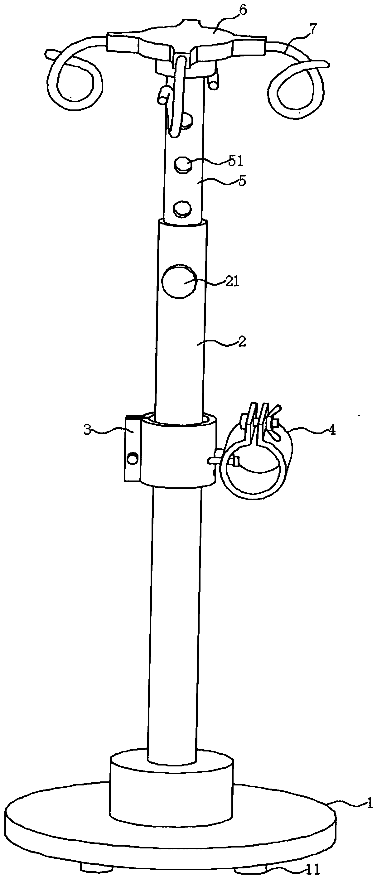
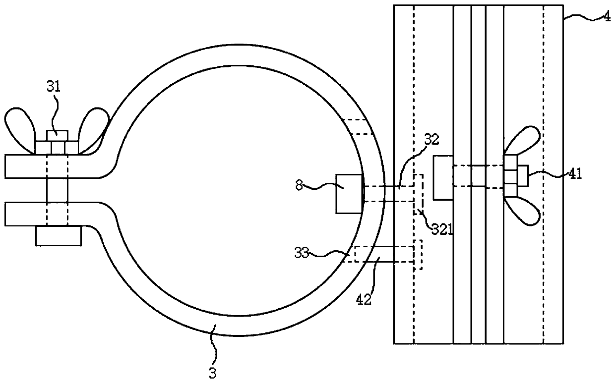
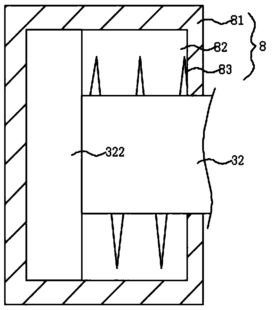
[0020] see Figure 1-3 , the present invention provides a technical solution: a stable infusion stand, including a base 1, the upper end of the base 1 is threadedly connected with a support rod 2, and the bottom end of the base 1 is provided with a foot 11, the base 1 and the support rod 2. It is detachable, so that the bottom end of the support rod 2 can be inserted on the bed frame at the lower part of the mobile hospital bed. The bottom end of the foot 11 has a screw hole, and the foot 11 can be threaded to connect mobile equipment such as rollers. The side of the support rod 2 The upper part of the wall is screwed into the limit bolt 21, and the upper end of the support rod 2 is movably inserted with the insertion rod 5, and the side wall of the insertion rod 5 is equidistantly provided with a number of limit screw holes 51, and the limit bolt 21 end through the limit screw hole 51, by inserting the limit bolt 21 into the limit screw hole 51 at different positions to adjus...
Embodiment 2
[0023] see figure 1 , 2and 4, the present invention provides another technical solution: the adjustment member 8 includes a second adjustment cap 84, a second adjustment cavity 85, a first ring magnet 86 and a second ring magnet 87, and the right end of the second adjustment cap 84 A second adjustment cavity 85 is opened, the first ring magnet 86 is fixedly connected to the right end of the block 322 , and the second ring magnet 87 is fixedly installed on the right end of the inner wall of the second adjustment cavity 85 . The magnetic poles on the opposite sides of the first ring magnet 86 and the second ring magnet 87 are the same, and pulling the second hoop 4 can drive the pin shaft 32 to move to the right along the second adjustment cavity 85, so that the stopper 322 can move to the right side. The right side of the first adjustment chamber 82 moves, so that the stop screw 42 can be driven to break away from the stop hole 33, and the rotation of the second hoop 4 can be ...
PUM
 Abstract
Description
Claims
Application Information
 - R&D
- Intellectual Property
- Life Sciences
- Materials
- Tech Scout
- Unparalleled Data Quality
- Higher Quality Content
- 60% Fewer Hallucinations
Browse by: Latest US Patents, China's latest patents, Technical Efficacy Thesaurus, Application Domain, Technology Topic, Popular Technical Reports.
© 2025 PatSnap. All rights reserved.Legal|Privacy policy|Modern Slavery Act Transparency Statement|Sitemap|About US| Contact US: help@patsnap.com


