Eureka AIR delivers breakthrough ideas for toughest innovation challenges, trusted by R&D personnel around the world.

A nozzle steering mechanism and a plastic tank cleaning device using the nozzle steering mechanism

A technology of steering mechanism and nozzle, which is applied in the direction of cleaning hollow objects, cleaning methods and utensils, chemical instruments and methods, etc., can solve the problems of low cleaning efficiency, large waste of water resources, poor cleaning effect, etc., and achieve good high-pressure flushing effect , High degree of automation, guarantee comprehensive effect

Active Publication Date: 2021-02-19
成都慧晶机械设备有限公司
View PDF15 Cites 0 Cited by
  • Summary
  • Abstract
  • Description
  • Claims
  • Application Information

AI Technical Summary

Problems solved by technology

[0004] 1. The cleaning efficiency is low, requiring a lot of manpower to clean the glue tank repeatedly, and the cleaning is not thorough, and the cleaning effect is not good;
[0005] 2. The waste of water resources is large. Each glue tank needs a large amount of water to be washed once, and the recycling of water resources cannot be achieved multiple times.

Method used


Image

  • A nozzle steering mechanism and a plastic tank cleaning device using the nozzle steering mechanism
  • A nozzle steering mechanism and a plastic tank cleaning device using the nozzle steering mechanism
  • A nozzle steering mechanism and a plastic tank cleaning device using the nozzle steering mechanism

Examples


Embodiment 1

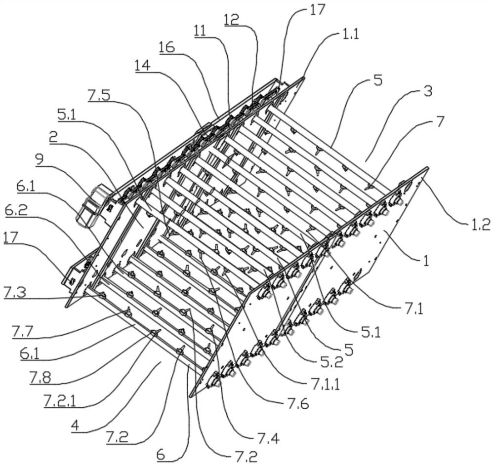
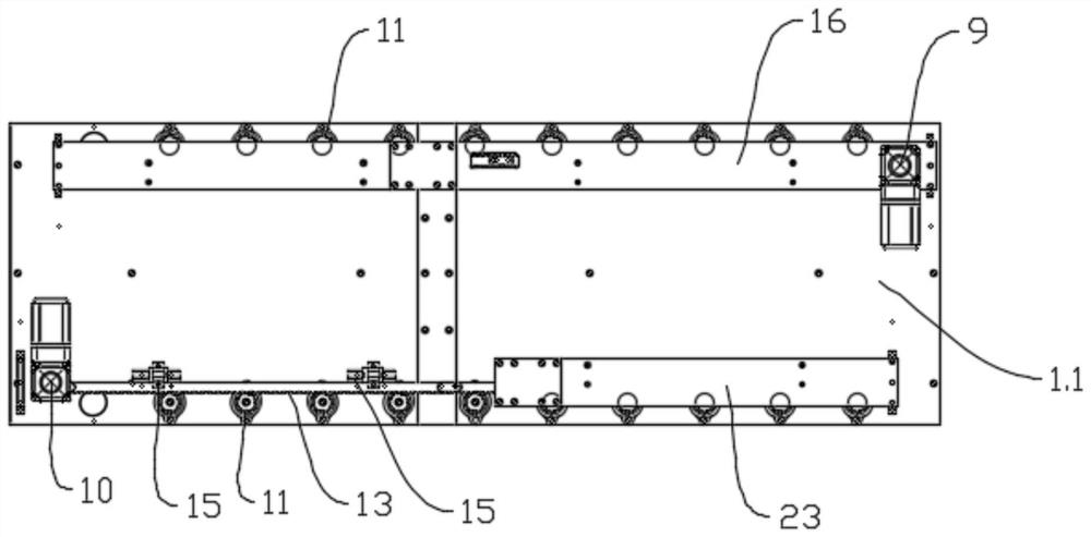
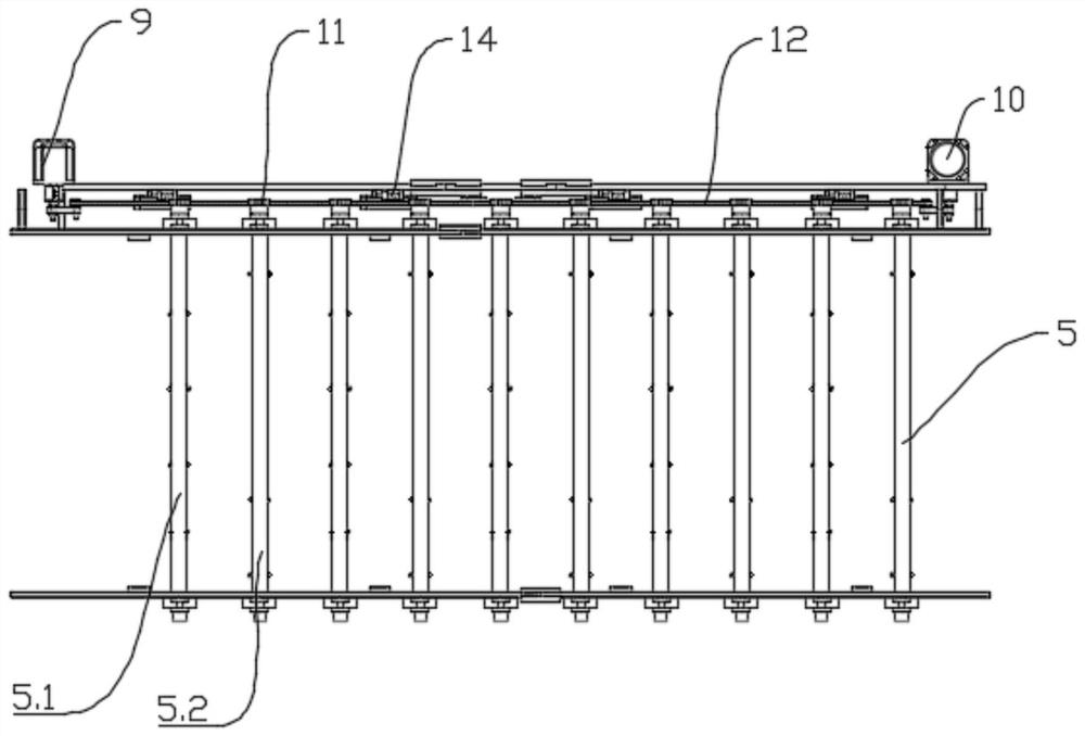
[0043] Such as Figure 1-Figure 7 As shown, this embodiment provides a nozzle steering mechanism, which includes a mounting frame 1, and the mounting frame 1 is provided with an upper installation position, a lower installation position below the upper installation position, and a cleaning device between the upper installation position and the lower installation position. Area 2, cleaning area 2 is provided with inlet end 3 and outlet end 4, and the upper installation position is provided with a plurality of rotating shafts 15, and the lower installation position is provided with a plurality of rotating shafts 26, a plurality of rotating shafts 5 and 6 They are all arranged side by side in the direction from the inlet end 3 to the outlet end 4. The first rotating shaft 5 and the second rotating shaft 6 are rotationally connected with the installation frame 1, and the first rotating shaft 5 and the second rotating shaft 6 are provided with a nozzle 7. The nozzles of 7 are all t...

Embodiment 2

[0049] This embodiment is optimized and defined on the basis of the above-mentioned embodiment 1.

[0050] Such as Figure 1-Figure 7 As shown, the nozzle 7 set on the rotating shaft 5 is the nozzle 1 7.1, the nozzle 7 provided on the rotating shaft 6 is the nozzle 2 7.2, and the nozzle 7.1 is evenly arranged in multiples along the length direction of the rotating shaft 5. Two nozzles 7.2 are evenly arranged in multiples along the length direction of the rotating shaft two 6 .

[0051] Nozzle 1 7.1 and Nozzle 2 7.2 adopt a uniformly arranged structure, which can achieve thorough cleaning of each surface of the glue tank.

[0052] Specifically, in this embodiment, there are 4 nozzles 1 7.1 on the first rotation axis 5, and 4 nozzles 2 7.2 on the rotation axis 2 6.

Embodiment 3

[0054] This embodiment is optimized and defined on the basis of the above-mentioned embodiment 2.

[0055] Such as Figure 1-Figure 7 As shown, the upper mounting position and the lower mounting position are intersected with odd-numbered rotating shaft positions and even-numbered rotating shaft positions, and the rotating shaft one 5 and rotating shaft two 6 installed on the odd-numbered rotating shaft positions are respectively odd-numbered rotating shaft 1 5.1 and odd-numbered rotating shaft Two 6.1, the first rotating shaft 5 and the second rotating shaft 6 installed on the even rotating shaft positions are the first even rotating shaft 5.2 and the second even rotating shaft 6.2;

[0056] Rotating shaft 1 5 and rotating shaft 2 6 are intersected with odd-numbered installation positions and even-numbered installation positions. Nozzle 1 7.1 is installed on the odd-numbered installation positions of odd-numbered rotational shaft 1 5.1 and on the even-numbered installation pos...


PUM


Abstract

The invention belongs to the technical field of cleaning equipment, and discloses a nozzle steering mechanism and glue vat cleaning equipment using the nozzle steering mechanism, including a mounting frame, which is provided with an upper installation position, a lower installation position below the upper installation position and a The cleaning area between the upper installation position and the lower installation position, the cleaning area is provided with an inlet end and an outlet end, the upper installation position is provided with a number of rotating shafts 1, the lower installation position is provided with a number of rotating shafts 2, a number of rotating shafts 1 and The two rotating shafts are arranged side by side sequentially from the inlet end to the outlet end, the first rotating shaft and the second rotating shaft are rotationally connected with the mounting frame, and the first rotating shaft and the second rotating shaft are provided with nozzles; the present invention can be used from different angles Realize the high-pressure water flushing of the glue tank, which has the advantages of good flushing effect, high cleaning efficiency, high utilization of water resources and saving water resources.

Description

technical field [0001] The invention belongs to the technical field of cleaning equipment, and in particular relates to a nozzle steering mechanism and glue tank cleaning equipment using the nozzle steering mechanism. Background technique [0002] After the cigarette packaging machine is used for 24 hours, a large amount of solidified glue will adhere to the inner wall of the glue tank and the accessory parts, and the glue tank needs to be cleaned in time. At present, domestic cigarette manufacturers are still using manual methods to clean the rubber tanks. In terms of cleaning methods, because the staff on duty use blades to manually scrape and cut the semi-solidified latex, the surface of the parts will be damaged and the life of the parts will be shortened. In terms of cleaning quality, due to the limitations of manual cleaning, it takes a lot of manpower to clean the glue tank several times. If some parts of the glue tank are not cleaned thoroughly, long-term accumulatio...

Claims


Application Information

Patent Timeline
Patent Type & Authority Patents(China)
IPC IPC(8): B08B9/093
Inventor 尹阳江章其张鹏程陈川李攀韦明勉丁健
Owner 成都慧晶机械设备有限公司
Why Eureka
Eureka Blog
Learn More