3D printing schedule display method for bridge engineering

A technology of 3D printing and bridge engineering, applied in the direction of processing and manufacturing, additive processing, etc., can solve the problems of large linear engineering length, unfavorable formation of schedule decisions, and limitations, and achieve the effect of improving accuracy and efficiency

Active Publication Date: 2019-05-03
BEIJING MUNICIPAL ROAD & BRIDGE
View PDF7 Cites 4 Cited by
  • Summary
  • Abstract
  • Description
  • Claims
  • Application Information

AI Technical Summary

Problems solved by technology

The traditional progress data table cannot intuitively express the visual progress of linear projects, limited by the screen size, and the progress pictures are not conducive to clearly and comprehensively displaying the visual progress of linear projects
[0003] If the traditional sand table is used to display the progress of the project image, the progress of the structures below the ground such as pile foundations and caps cannot be clearly displayed
At the same time, with the development of the project, the number of changes increases, requiring the sand table maker to frequently replace parts, making it difficult to match the actual progress in real time
And because the length of the linear project is long, the length of the sand table produced is also large, which leads to the failure of the production, the high cost and the abandonment, etc.
[0004] Based on the above situation, construction managers are often unable to quickly and accurately understand the overall progress of linear projects, and it is not convenient to accurately express intentions in progress management discussions, which is not conducive to accurate and efficient formation of progress decisions

Method used


Image

  • 3D printing schedule display method for bridge engineering
  • 3D printing schedule display method for bridge engineering
  • 3D printing schedule display method for bridge engineering

Examples


Embodiment Construction

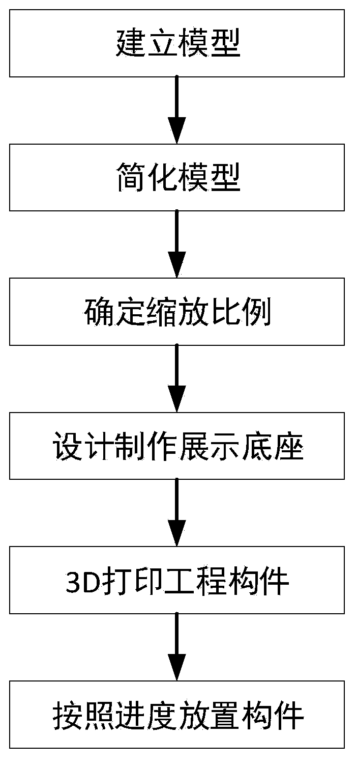
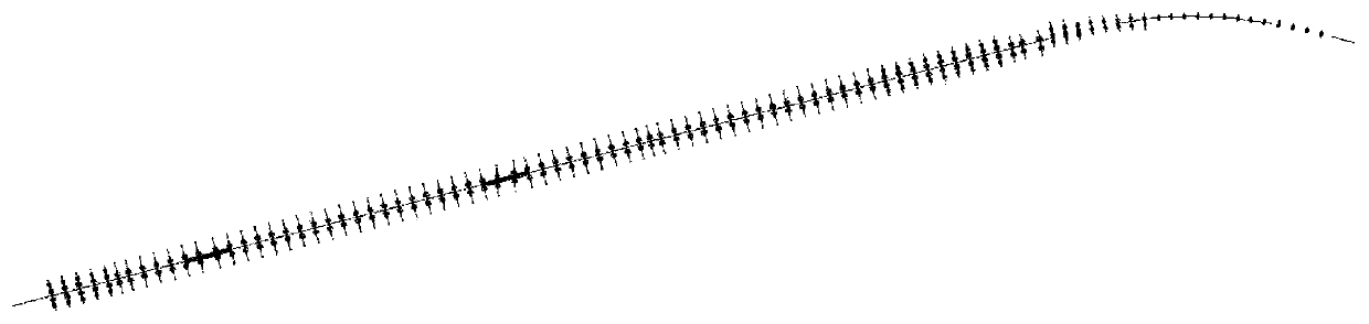
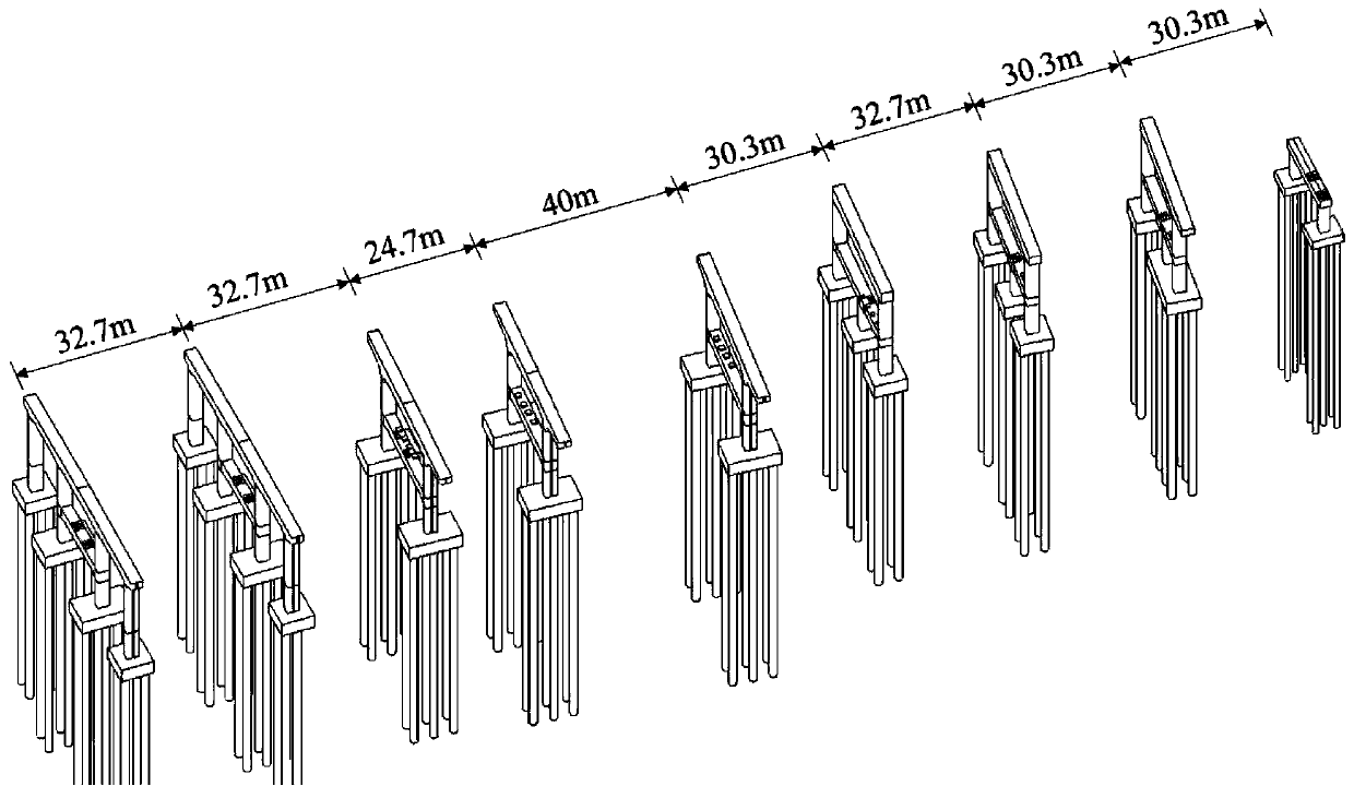
[0036] (1) According to the drawings, use the BIM software Revit to build a 3D model of the entire line structure, and the distance between the lower structures of each axis is different, such as figure 2 , image 3 shown.

[0037] (2) The bridge structure is simplified in Revit software, the height h from the bottom of the cap to the top of the lower structure is 25 meters, and the length of the pile foundation along the whole line is l 1 Unified as 0.6h, that is, 15 meters, the distance between the lower structures of the whole line is l 2 Unify 0.8h, that is, 20 meters, and the flat curve is simplified to a straight line. Get the mileage length L of the simplified model on the straight line 1 1820 meters, the maximum width D 1 is 50 meters. Such as Figure 4 , Figure 5 shown.

[0038] (3) The conference table of the project department can be used to display the length L of the device 2 6.2 meters, width D 2 is 0.6 meters. i 1 =L 2 / (L 1 +2l 2 )=1 / 300, i2=D ...


PUM

PropertyMeasurementUnit
lengthaaaaaaaaaa
widthaaaaaaaaaa

Abstract

The invention provides a 3D printing schedule display method for bridge engineering and relates to the field of bridge engineering. The method is used for synchronizing the engineering actual schedule, the visual schedule of engineering is displayed indoors, construction management personnel can grasp the overall schedule of the engineering conveniently, rapidly and accurately, and precise and efficient schedule decision making is achieved. According to the flow of the method, (1), an engineering three-dimensional model is set up according to sub-step and sub-item engineering division of an engineering drawing and a construction plan; (2), a bridge structure is simplified to form a simplified three-dimensional model; (3), the scaling proportion is selected; (4), according to the selected scaling proportion and the simplified three-dimensional model, the length of a display device, the number of middle sections, the length of an end section, the width of a base, holing of a top plate, shaft number marking and the distance between a base plate and the top plate are designed; (5), according to the simplified three-dimensional model and the sub-step and the sub-item division, all components of bridge engineering are printed in a 3D manner; and (6), the engineering actual schedule is synchronized, and the components, printed in a 3D manner, of bridge engineering are arranged in thedisplay device.

Description

technical field [0001] The method is applicable to bridge engineering construction in the field of highway and municipal infrastructure, and is used for indoor 3D printing to display the image progress of bridge engineering. Background technique [0002] Unlike traditional construction projects, most bridge projects in the field of highways and municipal infrastructure have long mileage and are often linear projects. The traditional progress data table cannot intuitively express the visual progress of linear engineering, limited by the screen size, and the progress picture is not conducive to clearly and comprehensively displaying the visual progress of linear engineering. [0003] If the traditional sand table is used to display the progress of the project image, the progress of the structures below the ground such as pile foundations and caps cannot be clearly displayed. At the same time, with the development of the project, the number of changes increased, requiring the ...

Claims


Application Information

Patent Timeline
Patent Type & Authority Applications(China)
IPC IPC(8): B29C64/10B33Y10/00
Inventor 邓博宁伟谷文元李杰李博森裴九超安红卫李昊
Owner BEIJING MUNICIPAL ROAD & BRIDGE
Why Eureka
Try Eureka