A steel pipe arch bridge suspender preformed hole accurate positioning device

A technology for precise positioning and steel pipe arch bridges, which can be used in bridges, bridge construction, erection/assembly of bridges, etc. It can solve the problems of high difficulty in laser alignment or total station measurement and inconsistent guarantee of accuracy, and achieve high positioning accuracy and convenience. The effect of the operation

Pending Publication Date: 2019-05-03
中铁二十一局集团第五工程有限公司
View PDF0 Cites 0 Cited by
  • Summary
  • Abstract
  • Description
  • Claims
  • Application Information

AI Technical Summary

Problems solved by technology

[0004] The existing technology is to use laser alignment or total station for accurate measurement. This technology is more suitable for straight section steel pipe arch bridges without any longitudinal slope. Position or total station measurement is difficult, and the accuracy is not guaranteed

Method used


Image

  • A steel pipe arch bridge suspender preformed hole accurate positioning device
  • A steel pipe arch bridge suspender preformed hole accurate positioning device

Examples


Embodiment 1

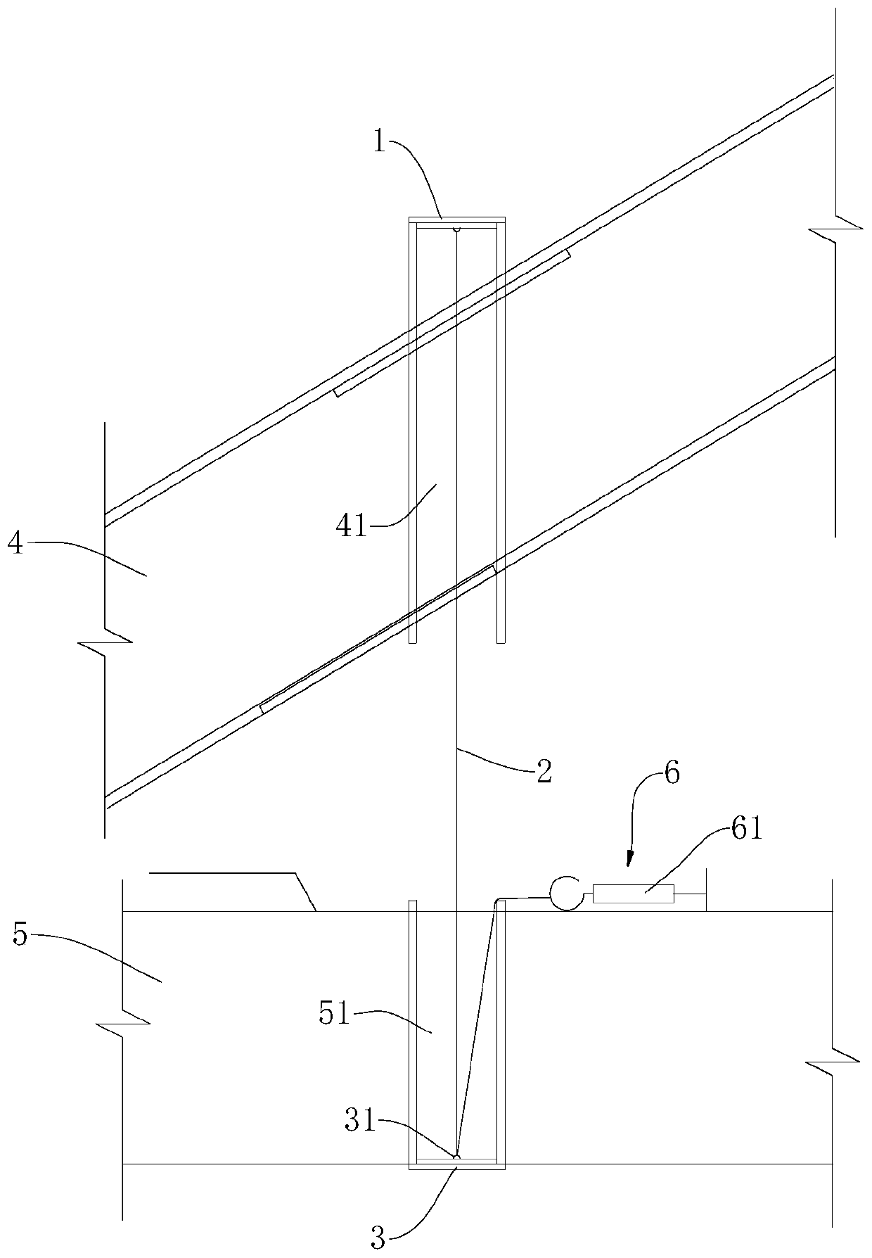
[0020] This embodiment provides a precise positioning device for the reserved hole of the suspender of a steel pipe arch bridge, the structure of which is shown in the figure.

[0021] The precise positioning device for the reserved hole of the steel pipe arch 4 bridge suspender includes the steel wire rope 2 passing through the upper reserved through hole 41 and the lower reserved through hole 51 in sequence, the upper reserved through hole 41 is located on the steel pipe arch 4, and the lower reserved through hole The reserved through hole 51 is located on the beam surface 5, and the two ends of the steel wire rope 2 are respectively set on the central axis of the upper reserved through hole 41 and the lower reserved through hole 51, and the steel wire rope 2 passes through the lower reserved through hole 51 and is connected and tensioned. Part 6, the tension part 6 keeps the wire rope 2 in tension.

[0022] The top of the upper reserved through hole 41 is provided with a st...

Embodiment 2

[0025] A method for locating steel pipe arches and beam surfaces using the precise positioning device of any of the above schemes,

[0026] Pass a steel wire rope 2 through the upper reserved through-hole 41 and the lower reserved through-hole 51 in sequence, respectively fix it on the upper end of the steel pipe arch 4 and the lower end of the beam surface 5, measure the lower opening of the upper reserved through-hole 41 and the lower reserved through-hole respectively 51 catchable deviation, adjust the position of the steel pipe arch 4 accordingly until the requirements are met.

[0027] The present invention avoids the space position deviation between the upper reserved through-hole 41 and the lower reserved through-hole 51 , causing the rigid suspender to be out of position during installation, and ultimately resulting in uneven stress after the suspender is stretched, affecting the durability of the suspender. When the steel pipe arch 4 is installed, it operates synchron...


PUM


Abstract

The invention discloses a steel pipe arch bridge suspender preformed hole accurate positioning device, and relates to the technical field of bridge engineering positioning devices. The steel pipe archbridge suspender preformed hole accurate positioning device comprises a steel wire rope that sequentially penetrates through an upper preformed through hole and a lower preformed through hole, wherein the upper preformed through hole is located in a steel pipe arch, the lower preformed through hole is located in a beam surface, two ends of the steel wire rope are arranged on a center shaft of theupper preformed through hole and a center shaft of the lower preformed through hole respectively, and the steel wire rope penetrates out of the lower preformed through hole and is connected with a tensioning part that keeps the steel wire rope in a tensioned state. The position of the preformed through hole can be corrected in the alignment process of an embedded pipe of the steel pipe arch and an embedded pipe of the beam surface, and the mounting precision and the mounting efficiency are improved.

Description

technical field [0001] The invention relates to the technical field of bridge engineering positioning devices, in particular to a precise positioning device for reserved holes of steel pipe arch bridge suspenders. Background technique [0002] The bridge structure consists of steel tube arches and beam decks connected by suspenders. When installing, move the steel pipe arch and beam surface first, and there are through holes for the suspender to pass through on the steel pipe arch and beam surface. [0003] Before installing the suspender, it is necessary to pre-fix the steel pipe arch and beam surface, and then use a laser to pass through the corresponding two through holes to check whether the positions of the two through holes are correct. If there is a deviation in the positions of the two through holes, it is necessary to continue to move the steel pipe or beam surface for adjustment. [0004] The existing technology is to use laser alignment or total station for accu...

Claims


Application Information

Patent Timeline
Patent Type & Authority Applications(China)
IPC IPC(8): E01D21/00
Inventor 张生彦杜逢春陈晨吴建国李军昌常小平王增虎汪凌云赵昆蛟
Owner 中铁二十一局集团第五工程有限公司
Why Eureka
Try Eureka