Plain area highway abutment back structure, highway structure and construction method

A technology for expressways and plains, applied in infrastructure engineering, underwater structures, roads, etc., can solve the problems of difficult earthwork, restricting the progress of high-speed construction, etc., to reduce the impact, speed up the demand for backfill construction, and speed up the construction progress.

Pending Publication Date: 2022-04-12
SHANDONG TRAFFIC PLANNING DESIGN INST
View PDF4 Cites 0 Cited by
  • Summary
  • Abstract
  • Description
  • Claims
  • Application Information

AI Technical Summary

Problems solved by technology

The inventor also found that the current abutment back adopts an inverted ladder-type structure whose upper area is larger than the lower part. It is necessary to construct the conventional filling subgrade on both sides of the abutment back first, and then construct the abutment back. Due to the shortage of soil resources in plain areas, often It is all road and other soil, and the back of the abutment can only be constructed after the construction of the conventional soil subgrade. It is difficult to get the earth in place in time, and the source of soil restricts the high-speed construction progress.

Method used


Image

  • Plain area highway abutment back structure, highway structure and construction method
  • Plain area highway abutment back structure, highway structure and construction method
  • Plain area highway abutment back structure, highway structure and construction method

Examples


Embodiment 1

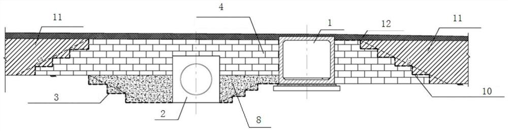
[0033] This embodiment provides a platform back structure of expressways in plain areas, such as Figure 1-Figure 2 As shown, including structures, the structures are buried in the backfill structure, and the two sides of the backfill structure are provided with filling subgrades, and the filling subgrade and the backfill structure together constitute the subgrade of the highway.

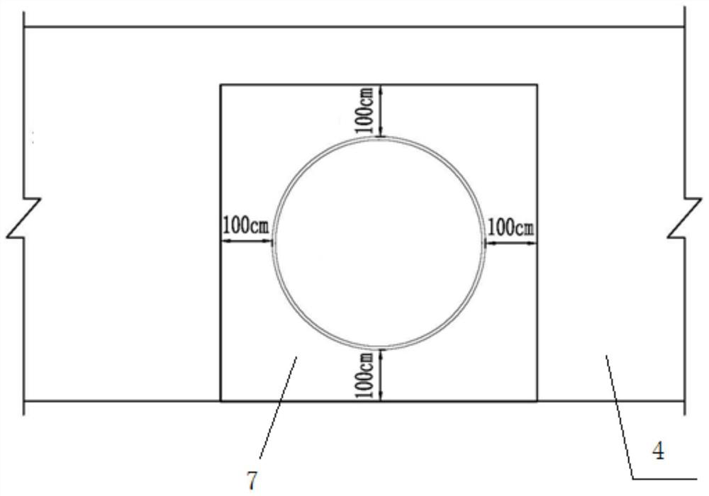
[0034] The structure is set according to actual needs. In this embodiment, two structures are included, namely the first structure 1 and the second structure 2, wherein the first structure 1 is a square box culvert, which is arranged on the base. As a common structure, another second structure 2 is a circular pipe box or a corrugated pipe box for drainage, and the circular pipe culvert or corrugated pipe culvert for drainage is laid in the foundation pit dug at the base.

[0035] In this embodiment, the two pit walls along the longitudinal direction of the road are provided with first stepped struct...

Embodiment 2

[0054] This embodiment provides a road structure, which is provided with the platform back structure of the expressway in the plain area described in Embodiment 1. Filled roadbeds 11 are arranged on both sides of the backfill structure to form the roadbed structure of the entire road structure, and the backfill structure has two sides. A composite geomembrane is arranged between the side step structure and the filling roadbed 11 to prevent the freezing and thawing of seepage water and capillary water in the filling roadbed.

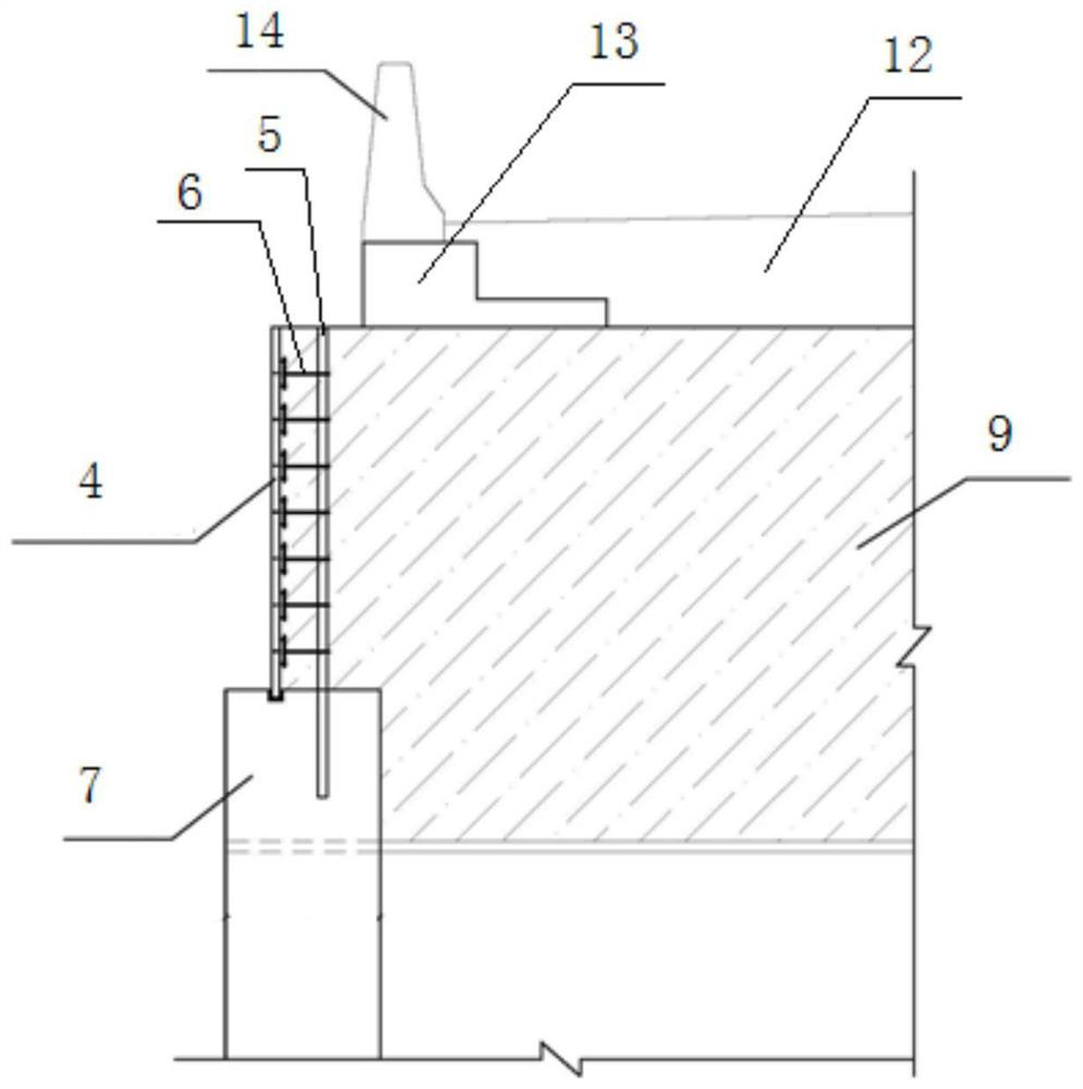
[0055] A pavement layer 12 is laid on the subgrade structure, and the pavement layer can adopt an existing pavement layer structure, and a guardrail foundation 13 and a guardrail 14 are arranged on the pavement layer.

Embodiment 3

[0057] This embodiment provides a construction method for the road structure described in Embodiment 2, comprising the following steps:

[0058] Step 1: Excavate the foundation pit at the base, excavate the two pit walls along the longitudinal direction of the road to form the first stepped structure 3, after treating the base, pour the foundation and platform of the first structure and the second structure After the concrete strength of the first structure and the second structure reaches 100%, the construction of the structures is completed.

[0059] Step 2: Pour reinforced concrete protective wall 8 at the end of the foundation pit, pour reinforced concrete protective wall 8 to the reinforced concrete protective wall 8 to level the top surface of the foundation pit, and then start building retaining wall 4 . When the retaining wall 4 is built by masonry, the retaining wall 4 is built into a trapezoidal wall with a narrow top and a wide bottom, and its side parts form a step...


PUM


Abstract

The invention relates to a plain area expressway abutment back structure, a highway structure and a construction method.The plain area expressway abutment back structure comprises a backfill structure and a structure located in the backfill structure, the section of the backfill structure is trapezoidal, the top face area of the backfill structure is smaller than the bottom face area of the backfill structure, the backfill structure comprises at least two retaining walls, and the retaining walls are arranged in the width direction of a highway; by adopting the abutment back structure disclosed by the invention, the construction speed is high, and the requirements of the abutment back of the expressway in the plain area are met.

Description

technical field [0001] The invention relates to the technical field of roads and bridges, in particular to an expressway platform back structure in plain areas, a road structure and a construction method. Background technique [0002] The statements herein merely provide background information related to the present invention and do not necessarily constitute prior art. [0003] In the plain area, there are dense roads for machine farming and many irrigation ditches between farmlands. When designing highways, in order to meet the needs of local villagers for production, living, drainage and irrigation, and at the same time reduce the design elevation of the overall longitudinal section of the highway and reduce the overall cost, many small structures such as round pipe culverts, corrugated pipe culverts, and slab culverts were laid out. things. [0004] Due to dense small-scale structures on expressways in plain areas, multi-segment short-circuit foundations are formed in ...

Claims


Application Information

Patent Timeline
Patent Type & Authority Applications(China)
IPC IPC(8): E01C3/00E01C3/06E02D29/02E02D17/04E01F5/00
Inventor 王健张冉于坤张凌涛孙玉海柳磊宋晓莉宋玉鑫刘杉李本鹏崔玉桥夏增选娄文杰韩宜均邓煜李帅
Owner SHANDONG TRAFFIC PLANNING DESIGN INST
Why Eureka
Try Eureka