Concrete forming system and method

a concrete and forming system technology, applied in the direction of girders, building repairs, auxiliary members of forms/shuttering/falseworks, etc., can solve the problems of affecting the easy and uniform flow of concrete, etc., to achieve convenient and convenient use, simplify construction accuracy, and simplify location and measurement

Inactive Publication Date: 2005-08-23
OLSEN TIMOTHY A
View PDF53 Cites 38 Cited by
  • Summary
  • Abstract
  • Description
  • Claims
  • Application Information

AI Technical Summary

Benefits of technology

[0015]At present, when traditional nail or screw fastenings are used with conventional concrete walls, fastening elements need to be established on the surface of the concrete structure as a secondary complex operation The system of the invention solves this problem by providing elongate linear fastening areas or strips that are typically placed in parallel relationship identical to traditional stick-frame “studs in a wall” construction. To simplify location and measurement each fastening strip and element of the inventive system is preferably provided with visually exposed measurement markings to simplify construction accuracy.
[0016]An important problem with the use of conventional concrete panels in lighter construction has been in providing an economical and easy-to-use method for forming without waste of material. Forming structure has typically been formed with wooden members, which generally have wasted much material and excessive waste of labor. The elimination of this waste is inherent in the inventive system, which maximizes economies. In the past, various reusable, normally modular forming systems have been introduced. These systems have generally been quite expensive and have required substantial expertise, preventing their general acceptance. There is no necessity for additional forming elements that do not become a part of the ultimate structure and the process, and avoids the waste of discarded forming material. The simplicity and “user friendly” precision is the major attribute of the inventive system

Problems solved by technology

During that history improvements have been introduced, yet there still remain drawbacks and deficiencies with conventional practice of forming concrete structures and the results obtained.
The conventional form of concrete construction has not become popular or extensively used with lighter construction for smaller buildings and various lighter applications, such as small office buildings, low-rise multi-dwelling units and individual residential housing units because of aesthetic limitations imposed.
Each of these has addressed the problem in similar fashion with molded shapes with integral spreaders and or webs between the exterior and interior surfaces, having molded hollows and pockets into which the concrete is placed, but which impede the easy and uniform flow of concrete introduced therein.
A further problem with known concrete forming systems employing foam blocks, is that the light weight of the foam blocks can lead to the forms being blown over by high winds even before the concrete is poured.
This is a particular problem in areas of flat terrain, where high winds occur more frequently.

Method used


Image

  • Concrete forming system and method
  • Concrete forming system and method
  • Concrete forming system and method

Examples


Embodiment Construction

[0033]The system consists of a number of components, and each of these will be considered in turn.

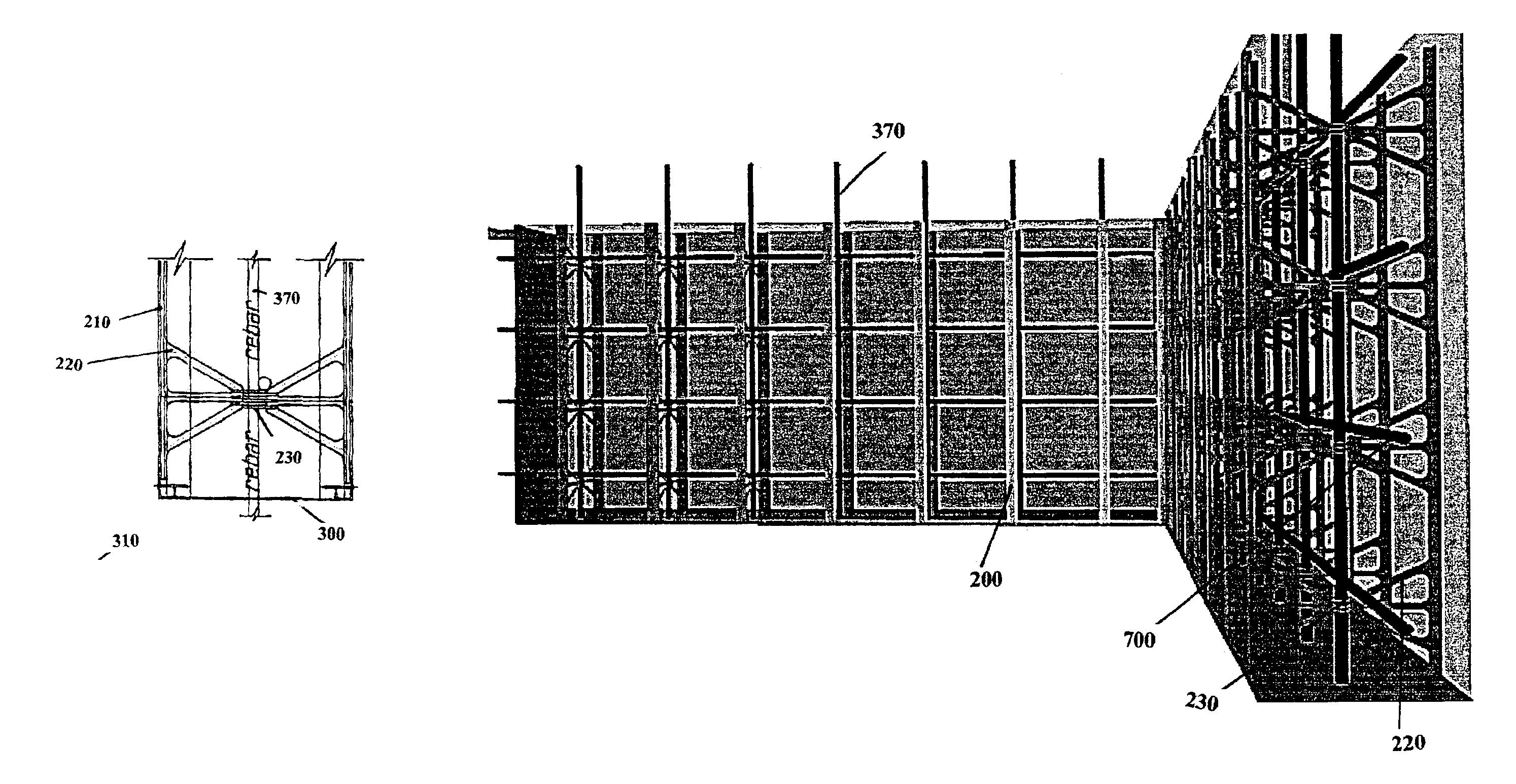
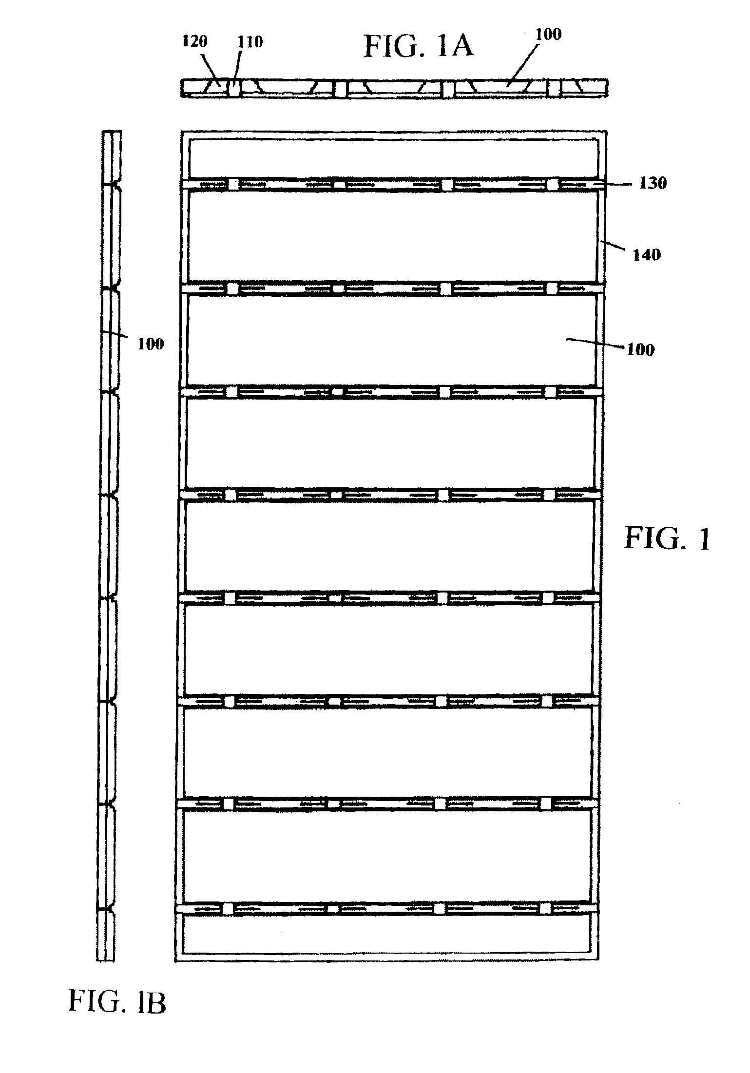
[0034]The foam forming Panel will first be considered. This typically consists of a 4×8-foot sheet of plastic foam in standard thickness, but may be of any practical dimension, and may be made from any suitable material. It has cutouts on 8 inch or 12 inch standard centers, or other centers as desired, including metric, to accept and locate the Joining and Fastening Strips of the invention. They may be installed in varying thickness, for example, a 3 inch thick panel on the exterior face, and a 2-inch thick panel on the interior face, as desired to provide the best thermal performance. See FIGS. 1, 1A and 1B. FIG. 1B shows a view of one corner of the assembled system as an example. FIGS. 7 and 8 similarly show computer generated perspective views

[0035]The Joining and Fastening Strips will be considered next. These are preferably manufactured from reclaimed plastic with appropriate fille...


PUM


Abstract

A system and method for forming concrete structures, using foam panels as forms, supported by vertical tracks with horizontal bridge pieces inserted through the forms. The bridge pieces are in the form of triangular webs with coaxial rings for supporting vertical rebars centrally between opposing forms. The coaxial rings on opposing bridge pieces key together to securely hold the vertical rebars. At the corners of the structure, corner retaining extrusions are used having fins for retaning the foam panels, and having various included angles such as 60°, 75°, 90°, 120°, 135°, 150° or 165°. Specific types of corner tie pieces for square, obtuse or acute corners are used to connect together the corner retaining extrusions at the inner and outer corners of the structure.

Description

FIELD OF THE INVENTION[0001]The invention relates to a forming system for concrete structures. More particularly, the invention relates to building structures using foam panels as formsDESCRIPTION OF THE BACKGROUND ART[0002]Historically, concrete structure has long been used for enduring, damage resistant construction. During that history improvements have been introduced, yet there still remain drawbacks and deficiencies with conventional practice of forming concrete structures and the results obtained.[0003]The shortcomings of conventional forming methods include waste of material, time and labor in forming and the required additional structures for attachment of “finish”. Various methods to address these have been utilized but none of these methods have been as simple and standardized as the solution presented by the present invention.[0004]The conventional form of concrete construction has not become popular or extensively used with lighter construction for smaller buildings and...

Claims


Application Information

Patent Timeline
Patent Type & Authority Patents(United States)
IPC IPC(8): E04B2/86
CPCE04B2/8647E04B2002/867
Inventor OLSEN, TIMOTHY A.
Owner OLSEN TIMOTHY A
Why Eureka
Try Eureka