Corrugated steel webplate combined box girder floor system for cable-stayed bridge and construction method thereof

A corrugated steel web, combined box technology, applied in cable-stayed bridges, bridges, bridge parts, etc., can solve the problem of affecting the mechanical performance of new and old concrete joints, difficult to guarantee the quality of concrete pouring, and reducing structural bearing capacity and stiffness. problems, to reduce the wet work workload and construction difficulty, the overall performance is good, and the construction is fast.

Inactive Publication Date: 2010-10-20
TSINGHUA UNIV
View PDF5 Cites 38 Cited by
  • Summary
  • Abstract
  • Description
  • Claims
  • Application Information

AI Technical Summary

Problems solved by technology

The slab end of the precast concrete slab (10) needs to be made into a toothed notch, and there are problems such as on-site operation and construction difficulty. Pouring quality is difficult to guarantee, which affects the mechanical performance of the joint between new and old concrete
On the other hand, the solid-web flat steel plate is used as the main girder web, and the steel girder has a restraining effect on the shrinkage and creep effect of the concrete bridge deck, which is easy to cause cracking of the bridge deck, thereby reducing the bearing capacity and stiffness of the structure, and affecting the structure. Durability
These problems have caused certain difficulties to the popularization and application of this type of structure.

Method used


Image

  • Corrugated steel webplate combined box girder floor system for cable-stayed bridge and construction method thereof
  • Corrugated steel webplate combined box girder floor system for cable-stayed bridge and construction method thereof
  • Corrugated steel webplate combined box girder floor system for cable-stayed bridge and construction method thereof

Examples


Embodiment Construction

[0021] Below in conjunction with accompanying drawing, structure of the present invention, construction process are described further.

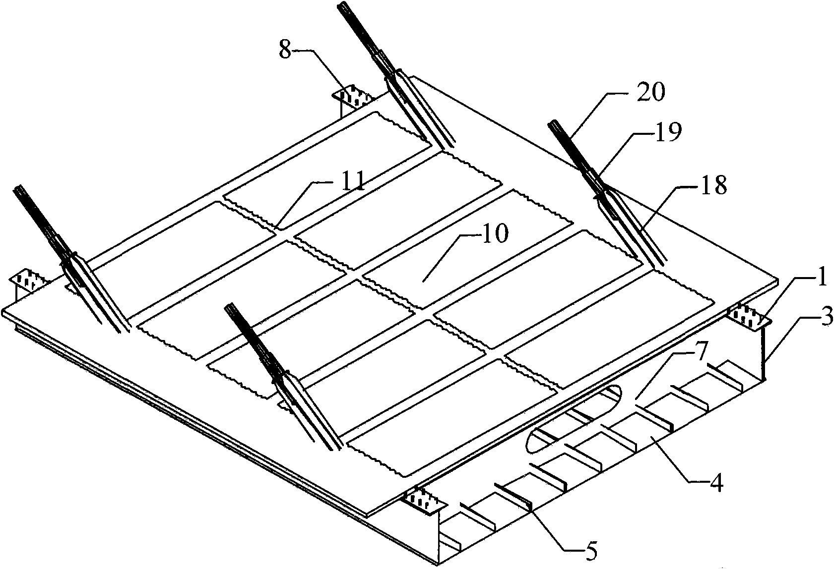
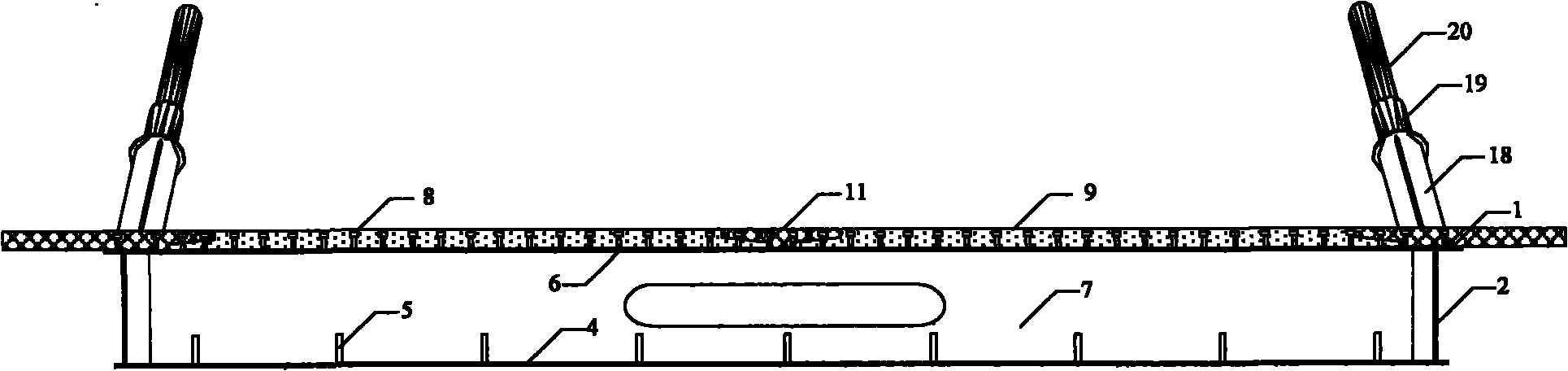
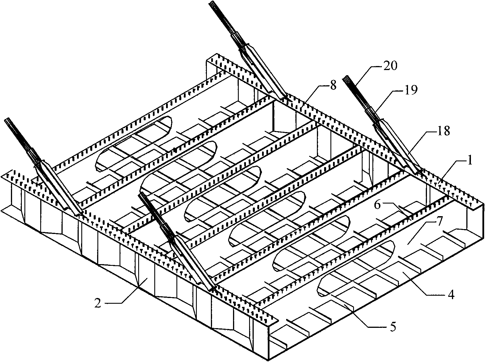
[0022] Compared with the traditional composite box girder deck system of cable-stayed bridges, the present invention provides less on-site workload and construction difficulty, easy guarantee of concrete pouring quality, higher structural bearing capacity, rigidity and crack resistance, and better economic performance Corrugated steel web composite box girder deck system of a cable-stayed bridge. Such as Figure 2 to Figure 7 As shown, the structure includes the steel box girder part of the composite box girder welded by the corrugated steel web 2, the upper flange steel plate 1, and the box girder bottom steel plate 4, and the box girder floor stiffener 5 is welded in the steel box girder And the diaphragm, the diaphragm includes the flange steel plate 6 on the diaphragm and the steel web 7 of the diaphragm; the stud connection is welded on...


PUM


Abstract

The invention relates to a corrugated steel webplate combined box girder floor system for a cable-stayed bridge and a construction method thereof, and belongs to the technical field of bridge structures. The corrugated steel webplate combined box girder floor system comprises a precast concrete plank and a cast-in-place concrete seam, wherein the precast concrete plank is positioned on a steel box girder and is integrated with the steel box girder into a whole; the steel box girder is formed by welding a top flange steel plate, a corrugated steel webplate and a steel plate at the bottom of the box girder; a box girder baseplate stiffening rib and a diaphragm plate are welded in the steel box girder; the diaphragm plate comprises a top flange steel plate of the diaphragm plate and a steel webplate of the diaphragm plate; a toggle pin connecting piece is welded on the top flange steel plate and the top flange steel plate of the diaphragm plate; and a steel anchor pulling plate and a steel sleeve are welded on the top flange steel plate. The corrugated steel webplate combined box girder floor system simplifies the manufacturing process for the precast concrete plank, gives full play to the superior mechanical property of the corrugated steel webplate and the release action of the corrugated steel webplate on the creep effect of concrete shrinkage, improves the bearing capacity, stiffness and crack resistance of the structure, and improves the durability of the structure.

Description

technical field [0001] The invention relates to a deck system of a long-span composite girder cable-stayed bridge applicable to highways and railways, and belongs to the technical field of bridge structures. Background technique [0002] Traditional composite box girder deck system of cable-stayed bridges, such as figure 1 As shown, it consists of prefabricated concrete slab (10), cast-in-place concrete joint (11), upper flange steel plate (1), flat steel web (3), box girder bottom steel plate (4), box girder floor stiffener ( 5), the flange plate on the diaphragm (6), the steel web of the diaphragm (7), the stud connector (8), the steel anchor pull plate (18) and the steel sleeve (19). The channel-shaped steel box girder is transported to the construction site for hoisting and positioning after welding at the factory. The slab end of the precast concrete slab (10) needs to be made into a toothed notch, and there are problems such as on-site operation and construction diff...

Claims


Application Information

Patent Timeline
Patent Type & Authority Applications(China)
IPC IPC(8): E01D19/12E01D2/04E01D21/00E01D11/04
Inventor 聂建国李法雄
Owner TSINGHUA UNIV
Why Eureka
Try Eureka