Annealing protecting pipe

A protection tube, annealing technology, applied in the direction of slender components, building components, etc., can solve the problems of cleaning, reducing production efficiency, unable to meet customers, etc., to achieve the effect of satisfying product quality and improving production efficiency

Pending Publication Date: 2019-05-03
WUXI TIANCHEN COLD DRAWING STEEL
View PDF0 Cites 0 Cited by
  • Summary
  • Abstract
  • Description
  • Claims
  • Application Information

AI Technical Summary

Problems solved by technology

The annealing furnace suitable for cold-drawn steel is generally an electric heating bell-type annealing furnace. This type of furnace has a relatively high cost performance. The only disadvantage is that it does not have a protective atmosphere. The annealed material has more scales, especially After annealing of some medium-carbon alloy steels and bearing steels, the surface is oxidized to form a spinel structure that is difficult to be removed by pickling and shot blasting
If the oxide skin on the surface cannot be effectively removed, it will not only reduce the production efficiency, but also affect the surface quality of the product, and ultimately cannot meet the needs of customers

Method used


Image

  • Annealing protecting pipe
  • Annealing protecting pipe
  • Annealing protecting pipe

Examples


Embodiment Construction

[0013] In order to make the purpose, technical solution and advantages of the present invention clearer, the present invention will be further described in detail below in conjunction with the accompanying drawings and specific embodiments.

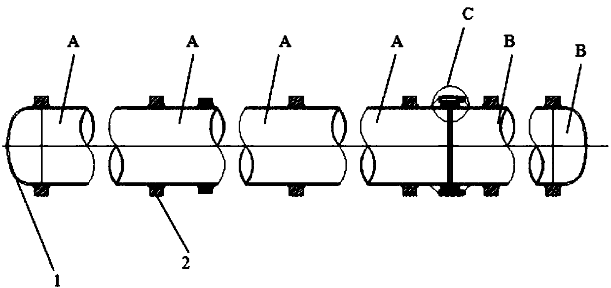
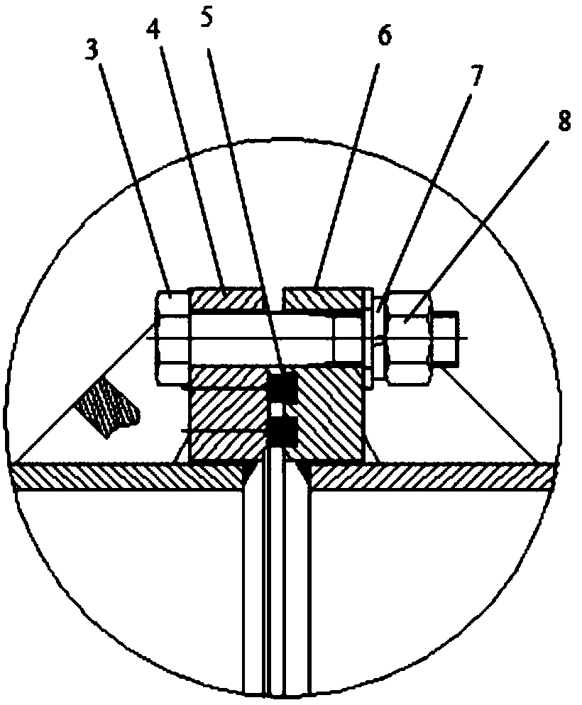
[0014] figure 1 is a schematic diagram of the overall structure of the annealing protection tube according to an embodiment of the present invention. figure 2 is according to the embodiment of the present invention figure 1 Enlarged view of the structure in region C.

[0015] An annealing protection tube provided by the present invention is composed of a first section A and a second section B, the ends of the first section A and the second section B are all provided with a spherical head 1, and the first section A first flange 4 and a second flange 6 are respectively provided at the junction of A and the second section B, and the first flange 4 and the second flange 6 are provided with connection holes and pass through the The connect...


PUM


Abstract

The invention provides an annealing protecting pipe which is composed of a first section and a second section. Spherical sealing heads are arranged on the end portion of the first section and the endportion of the second section correspondingly. A first flange and a second flange are arranged on the connecting portions of the first section and the second section correspondingly. The first flangeand the second flange are provided with connecting holes and are connected together in a fastened manner through the connecting holes. A sealing groove is formed in the end face of the second flange.An asbestos sealing ring is arranged in the sealing groove. By means of the annealing protecting pipe, in the whole annealing process of materials, the annealing protecting pipe can well isolate external oxidizing gas from entering, thus it is ensured that the materials are not oxidized in the whole annealing process, then the production efficiency is improved, and the product quality is met.

Description

technical field [0001] The invention relates to the mechanical field, in particular to an annealing protection tube. Background technique [0002] Cold drawing is a processing technology that applies external force to steel at room temperature to allow it to undergo plastic deformation to obtain the required external dimensions. During the cold deformation process of the metal, dislocations occur in the crystal grains, the deformation resistance increases and the properties deteriorate. During the multi-pass drawing process or the special performance annealing of the final product, intermediate annealing (recrystallization annealing) and finished product annealing must be carried out. The annealing furnace suitable for cold-drawn steel is generally an electric heating bell-type annealing furnace. This type of furnace has a relatively high cost performance. The only disadvantage is that it does not have a protective atmosphere. The annealed material has more scales, especial...

Claims


Application Information

Patent Timeline
IPC IPC(8): F16S3/00
Inventor 周兴亮王富国申勇峰孙月红刘一
Owner WUXI TIANCHEN COLD DRAWING STEEL
Why Eureka
Try Eureka