
Laser gyro based double-dynamic-target tracking guiding method

A laser gyroscope and dynamic target technology, applied in the field of target tracking, can solve problems such as the lack of a definite theoretical framework model and the lack of in-depth research on the tracking system

Active Publication Date: 2019-05-03
CHINA JIUYUAN HI TECH EQUIP
View PDF6 Cites 6 Cited by
  • Summary
  • Abstract
  • Description
  • Claims
  • Application Information

AI Technical Summary

Problems solved by technology

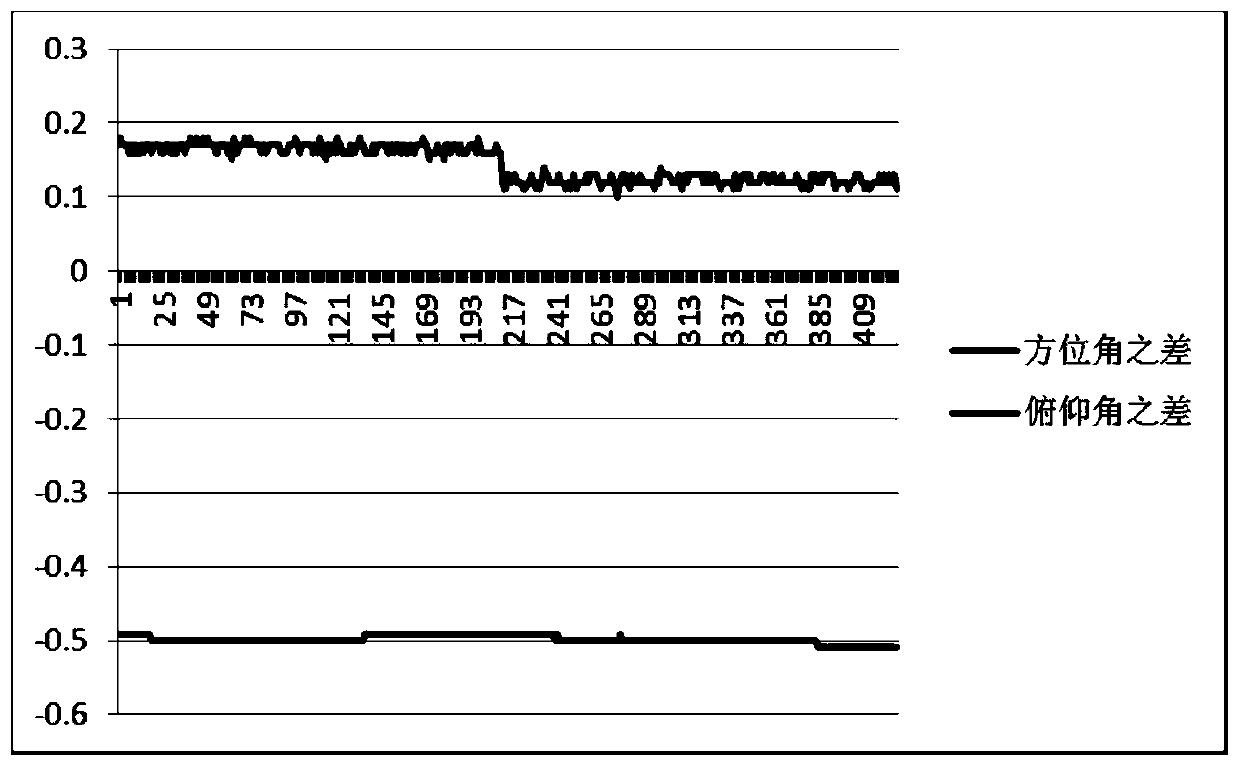
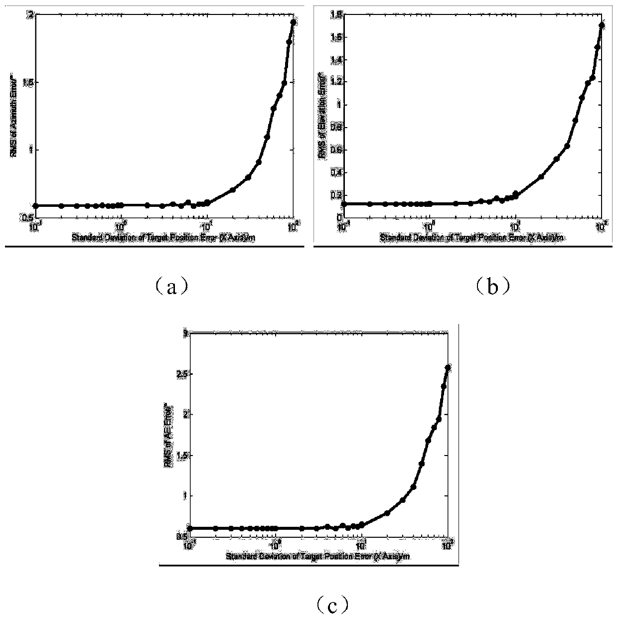
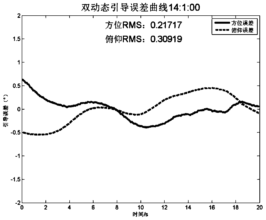
[0003] The purpose of the present invention is to provide a dual dynamic target tracking and guidance method based on laser gyroscopes, which is used to solve the situation in the prior art that the tracking system is on a dynamic platform, but no in-depth research has been carried out, and no definite operable theory has been formed. The problem with architectural models

Method used


Image

  • Laser gyro based double-dynamic-target tracking guiding method
  • Laser gyro based double-dynamic-target tracking guiding method
  • Laser gyro based double-dynamic-target tracking guiding method

Examples


Embodiment 1

[0040] As shown in the accompanying drawings, a laser gyroscope-based dual dynamic target tracking and guidance method includes the following steps:

[0041] Step 1: Obtain the GPS coordinates T of the target under the dynamic platform in real time G , the real-time GPS coordinates of the tracking system A G , the real-time pose of the platform (α, β, γ), the initial pose (α 0 ,β 0 ,γ 0 ), where α represents the heading angle, β represents the pitch angle, and γ represents the roll angle;

[0042] Step 2: Convert the ground-fixed coordinates of the target obtained in step 1 into the coordinates of the moving platform of the target. The conversion process first calculates the relative Based on the ground-like fixed coordinates of the moving platform, calculate the horizon coordinates of the target at the moving platform according to the ground-like fixed coordinates of the target relative to the moving platform and the GPS coordinates of the moving platform, and calculate t...


PUM


Abstract

The invention discloses a laser gyro based double-dynamic-target tracking guiding method. The method comprises the following steps that 1) a target GPS coordinate TG in a dynamic platform, a real-timeGPS coordinate AG of a tracking system, the real time attitude (alpha, beta, gamma) of the platform, and the initial attitude (alpha0, beta0, gamma0) are obtained in real time; 2) an earth-fixed coordinate of a target is transformed into a coordinate of a movement platform of the target; 3) a calibration horizon system and an axial system of the tracking system are converted to determine a transformation relation between axial system of the tracking system and the horizon system of the tracking system is obtained, and further a conversion angle from the horizontal system to the axial system of the tracking system is obtained; and 4) each inertial laser gyro is fixedly mounted in a random position of the platform, the tracking system is mounted on the platform, and the zero point of an encoder is not adjusted any more after installation. Only once calibration is needed, and the tracking system can be used directly in dynamic platform application later if the relative installation position is not changed any more, and a double-dynamic-target tracking guiding algorithm is reached to meet the requirements of dynamic target tracking guiding in the dynamic platform.

Description

technical field [0001] The invention relates to the technical field of target tracking, in particular to a laser gyroscope-based dual dynamic target tracking and guidance method. Background technique [0002] Target tracking guidance refers to the process of introducing dynamic flying targets in the air into the field of view of the photoelectric tracking system. The acquisition, tracking, and aiming of photoelectric targets are all carried out on the premise of guiding the target into the tracking field of view. Dual dynamic means that in addition to the dynamic flight of the target, the position and attitude of the platform where the tracking system itself is located also undergoes real-time dynamic changes. In this case, to achieve real-time guidance to the target, in addition to determining the position of the target in the air in real time, it is also necessary to grasp the position and attitude changes of the tracking system platform in real time. The dynamic target ...

Claims


Application Information

Patent Timeline
IPC IPC(8): G01C25/00
Inventor 王坤屈长虹陈兴无李芬陈林利伊炜伟高鑫
Owner CHINA JIUYUAN HI TECH EQUIP
Learn More