Damping valve for a vibration damper

A technology of damping valves and shock absorbers, which is applied in the field of damping valves, can solve problems such as the rise of damping force characteristic curves, and achieve the effects of simplified assembly, smooth extension, and reduced structural space requirements

Inactive Publication Date: 2019-05-03
ZF FRIEDRICHSHAFEN AG
View PDF1 Cites 1 Cited by
  • Summary
  • Abstract
  • Description
  • Claims
  • Application Information

AI Technical Summary

Problems solved by technology

The disadvantage is that, in the case of valve discs that tend to be rigid, a rise in the damping force characteristic curve occurs

Method used


Image

  • Damping valve for a vibration damper
  • Damping valve for a vibration damper
  • Damping valve for a vibration damper

Examples


Embodiment Construction

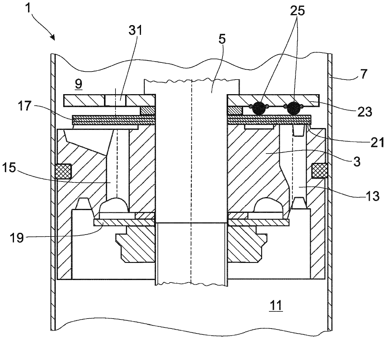
[0027] figure 1 A damping valve 1 for a shock absorber of any desired design is shown. The damping valve 1 includes a damping valve body 3 , and the damping valve body 3 is fixed on a piston rod 5 . The invention is not restricted to this type of embodiment and can be used, for example, in foot valves or also in the area of ​​adjustable damping valves.

[0028] The damping valve body 3 divides the cylinder 7 of the shock absorber into working chambers 9 , 11 close to the piston rod and remote from the piston rod, both of which are filled with damping medium. Throughflow channels 13 , 15 are embodied in the damping valve body 3 , respectively, for the flow directions on different pitch circles. The configuration of the through-flow channels is merely exemplary. The outlet side of the throughflow channel 13 , 15 is at least partially covered by at least one valve disk 17 , 19 .

[0029] Upon inflow into the valve disk 17 starting from the working chamber 11 facing away from ...


PUM


Abstract

The invention relates to a damping valve (1) for a vibration damper, comprising a damping valve body (3) that has at least one duct (13; 15), the discharge side of which is at least partially coveredby at least one valve disk (17; 19). When fluid flows against the at least one valve disk (17; 19) via the duct (13; 15), the valve disk lifts off from a valve seat surface (21), the lifting movementbeing limited by a supporting disk (23) as a stop; said supporting disk (23), in the direction of the valve disk (21), is equipped with an elastomer support (24) formed by a plurality of individual supporting elements (25). At least one individual support element (25) is formed from at least two individual elastomer elements (37; 39) which are combined into pairs to form an individual support element (25).

Description

technical field [0001] The invention relates to a damping valve according to the preamble of claim 1 . Background technique [0002] A damping valve for a shock absorber comprises a damping valve body having at least one through passage, the outlet side of which is at least partially covered by at least one valve disk. During flow into the valve side through the through-channel, the valve disk is lifted from the seat surface. In order to protect the valve disk against mechanical overload, at least one support disk is usually used as a stop limiting the lifting movement. In the simplest embodiment variant, the support disk is a simple, generally metallic, annular disk. In contrast, the valve disk is elastically deformable at the edge or is supported axially movable against a spring. Regardless of this embodiment, in damped operation, when a sudden peak load occurs, the effect is that the valve disk hits the support disk. This collision can be detected acoustically. [00...

Claims


Application Information

Patent Timeline
Patent Type & Authority Applications(China)
IPC IPC(8): F16F9/348
CPCF16F9/3485
Inventor A·科内泽维奇J·罗塞勒
Owner ZF FRIEDRICHSHAFEN AG
Why Eureka
Try Eureka