
Laser marking control system

A control system and laser marking technology, used in laser welding equipment, manufacturing tools, welding equipment, etc., can solve the problems of affecting the marking effect, high labor cost, time-consuming and laborious, etc., and achieve high work efficiency and marking position. Precise, quality-assured results

Inactive Publication Date: 2019-05-07
江苏昆太工业装备有限公司
View PDF8 Cites 1 Cited by
  • Summary
  • Abstract
  • Description
  • Claims
  • Application Information

AI Technical Summary

Problems solved by technology

Such an operation mode is time-consuming and labor-intensive, and the labor cost is high, and there will be mutual pushing when conveying, which will affect the marking effect

Method used


Image

  • Laser marking control system
  • Laser marking control system

Examples


Embodiment

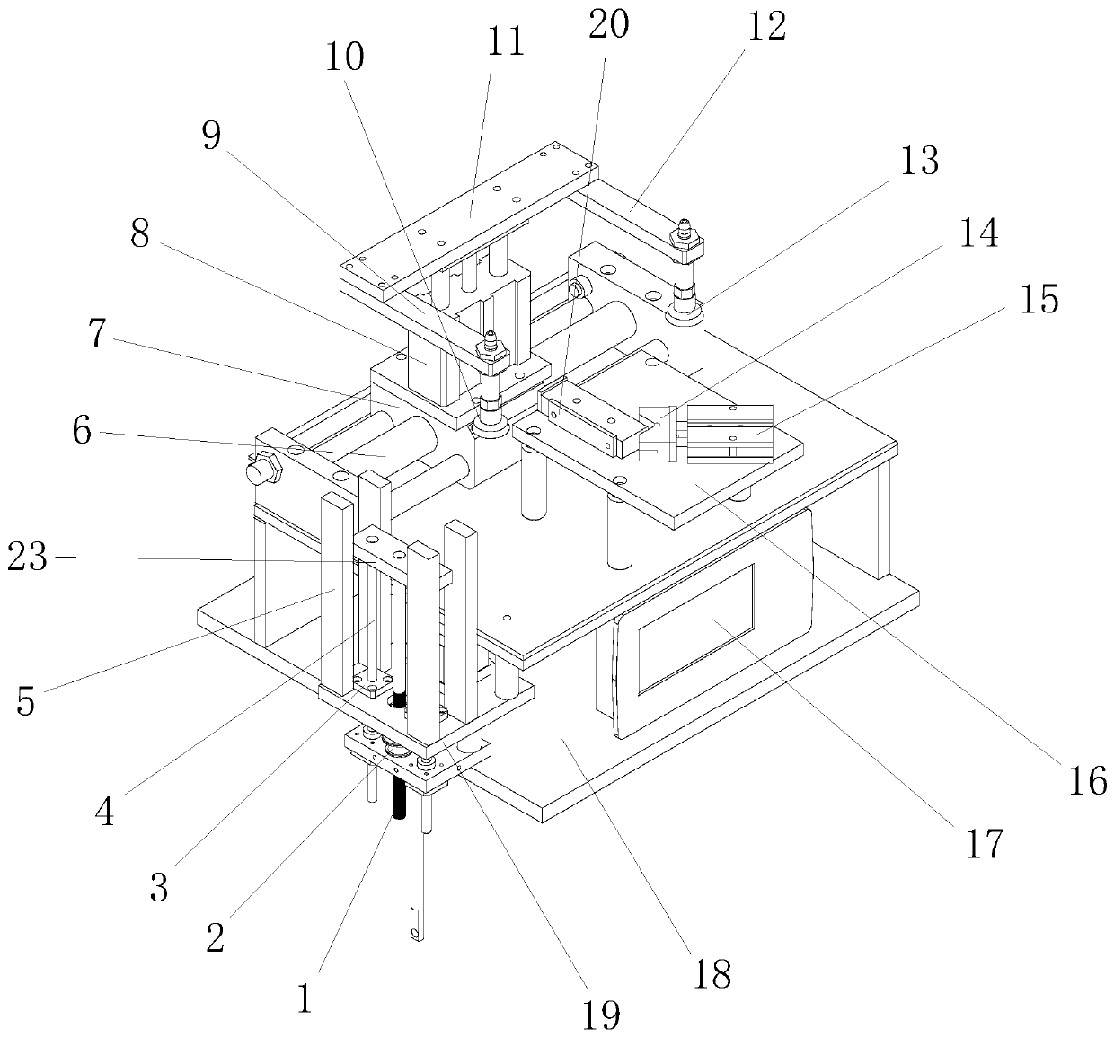
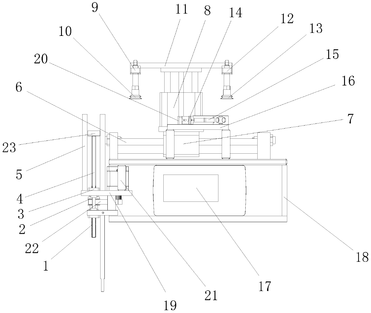
[0031] Such as Figure 1-2 As shown, a laser marking control system corresponds to the laser marking machine, and the control system is the core system for controlling the entire laser marking machine.

[0032] The laser marking machine includes a frame and a mounting plate arranged on the frame, and a mounting frame 16 is arranged on the mounting plate. An industrial computer 17, a touch screen and a negative pressure generator are installed in the mounting frame 16.

[0033] One side of the installation frame is provided with a jacking and feeding device, and the other side is provided with a finished product collecting device. The finished product collection device is a collection frame installed on the side of the installation frame. The jacking and feeding device includes a feeding plate 19 installed in the frame, and the feeding plate 19 is provided with four vertical fixing plates 5, and the four vertical fixing plates 5 form a frame for placing OEM products. A rotat...


PUM


Abstract

The invention discloses a laser marking control system which comprises a controller arranged in a rack, a rotating motor in a jacking loading device and a photoelectric detector for detecting height of a material, a sliding motor in a sliding driving device, a vertical lifting air cylinder in a lifting driving device, a positioning air cylinder in a driving positioning device and an infrared detector corresponding to the positioning air cylinder. The laser marking control system is reasonable in design, loads materials by way of automatic loading and suction by a suction disc, unloads the materials by way of suction by the suction disc and collects marked products in a collecting frame. In the full course, automatic marking and loading and unloading are achieved by means of a full-automatic control principle, so that the laser marking control system is time- and labor-saving and high in work efficiency, can replace manpower fully, is precise in marking position, guarantees the markingquality and is suitable for being popularized.

Description

technical field [0001] The invention belongs to the field of laser marking equipment, and more specifically relates to a laser marking control system. Background technique [0002] Laser marking is laser engraving of specific signs or logos. At present, there are various laser marking equipment. [0003] When marking sheet products, the laser marking machine is the best equipment, but the current laser marking machines rely on manual loading, then arrange, and then mark with the laser marking machine. Such an operation mode is time-consuming and labor-intensive, and the labor cost is high, and there will be mutual pushing when conveying, which will affect the marking effect. Contents of the invention [0004] Aiming at the deficiencies in the prior art, the object of the present invention is to provide a laser marking control system with reasonable design, automatic loading and sucker suction for loading, sucker sucking and unloading and collecting the marked products I...

Claims


Application Information

Patent Timeline
Patent Type & Authority Applications(China)
IPC IPC(8): B23K26/362B23K26/70
Inventor 孙亮
Owner 江苏昆太工业装备有限公司
Learn More