
Rack crankshaft variable speed transmission internal combustion engine

A variable speed transmission and internal combustion engine technology, which is applied in the direction of machines/engines, mechanical equipment, etc., can solve the problems of single speed and inability to switch between multiple speeds

Pending Publication Date: 2019-05-07
ZHANGJIAGANG CHUANJUN VEHICLE IND CO LTD
View PDF0 Cites 1 Cited by
  • Summary
  • Abstract
  • Description
  • Claims
  • Application Information

AI Technical Summary

Problems solved by technology

[0003] An internal combustion engine generally includes: a cylinder, a crankshaft, a connecting rod, a piston and a combustion chamber arranged in the cylinder, one end of the connecting rod is connected with the piston rod, the other end of the connecting rod is connected with the crankshaft, and the piston rod reciprocates in the cylinder To move back and forth, thereby driving the crankshaft to rotate, the internal combustion engine in the prior art has the following defects: the crankshaft is used as a power output part, and its output speed is relatively single, and it is impossible to switch between multiple speeds

Method used


Image

  • Rack crankshaft variable speed transmission internal combustion engine
  • Rack crankshaft variable speed transmission internal combustion engine
  • Rack crankshaft variable speed transmission internal combustion engine

Examples


Embodiment 2

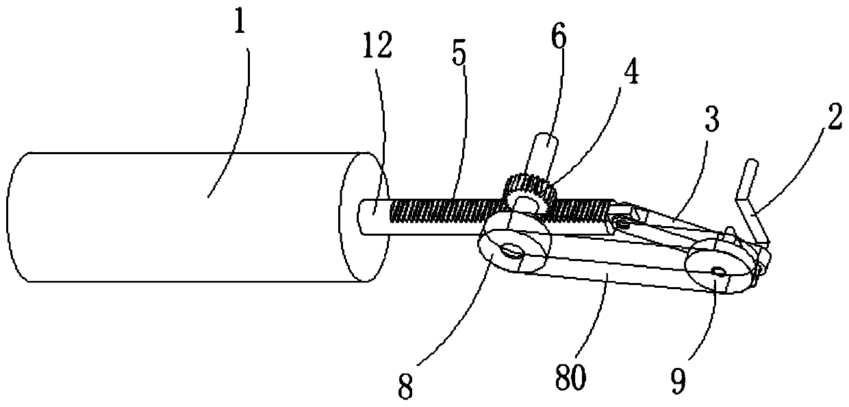
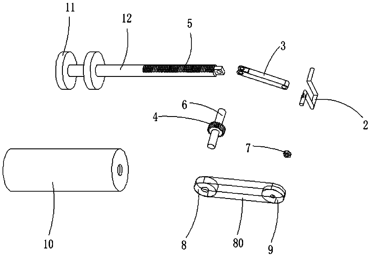
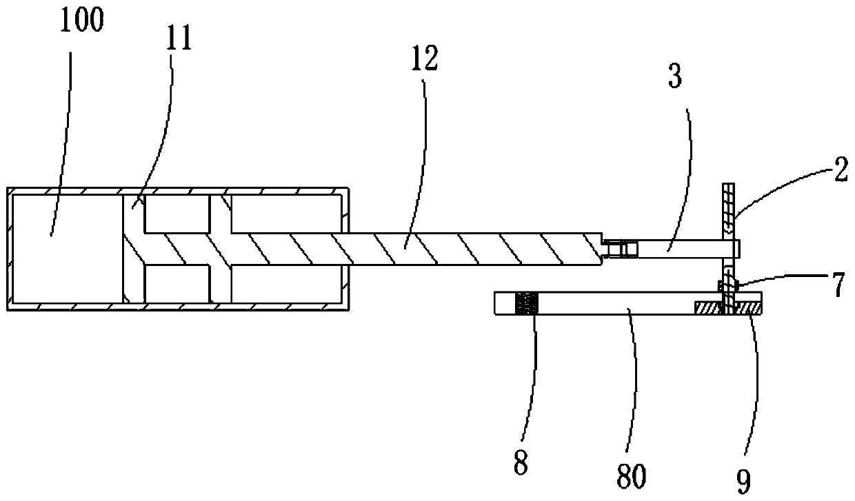
[0023] see Figure 4 , the rest of the structure in this embodiment is the same as that of Embodiment 1, the difference is that: in Embodiment 1, the first transmission wheel 8 is fixedly connected to the output shaft 6, and the second The transmission wheel 9 is sheathed on the crankshaft 2 and can rotate relative to the crankshaft 2 . In this embodiment, the engaging member 7 is sleeved on the output shaft 6 and is connected with the output shaft 6 in a radial transmission and axial direction. The first transmission wheel 8 is sleeved on the output shaft 6 and can be Rotating relative to the output shaft 6, the second transmission wheel 9 is fixedly connected to the crankshaft 2, which can also realize the present invention.

[0024] The working principle of the rack crankshaft variable speed transmission internal combustion engine in this embodiment is as follows: when the fuel burns in the combustion chamber, the piston of the cylinder 1 is pushed to move, and the piston ...


PUM


Abstract

The invention discloses a rack crankshaft variable speed transmission internal combustion engine. The rack crankshaft variable speed transmission internal combustion engine comprises a cylinder, a crankshaft, a connecting rod, a gear, a rack, an output shaft, an engagement piece, a first transmission wheel and a second transmission wheel; the cylinder comprises a cylinder block, a piston and a piston rod; a combustion chamber is arranged in the cylinder block; one end of the piston rod is connected with the piston, and the other end of the piston rod is connected with the rack; one end of theconnecting rod is movably connected with the rack, and the other end of the connecting rod is movably connected with the crankshaft; the engagement piece sleeves the output shaft or the crankshaft, and forms radial transmission and axial movable connection with the output shaft or the crankshaft; the first transmission wheel is arranged on the output shaft; the second transmission wheel is arranged on the crankshaft; the gear is engaged with the rack; the gear is arranged on the output shaft; and an overrunning clutch is arranged between the gear and the output shaft. The variable speed outputof the output shaft is realized.

Description

【Technical field】 [0001] The invention relates to the field of internal combustion engines, in particular to a rack crankshaft transmission internal combustion engine. 【Background technique】 [0002] An internal combustion engine is a kind of power machinery, which is a heat engine that directly converts the heat energy released by burning fuel inside the machine into power. The reciprocating piston internal combustion engine is the most common type of piston internal combustion engine. The piston internal combustion engine mixes fuel and air and burns it in its cylinder. The heat energy released makes the cylinder generate high temperature and high pressure gas. The expansion of the gas pushes the piston to do work, and then passes through the crank connecting rod. The mechanism outputs the mechanical work to drive the driven machine to work. [0003] An internal combustion engine generally includes: a cylinder, a crankshaft, a connecting rod, a piston and a combustion cha...

Claims


Application Information

Patent Timeline
Patent Type & Authority Applications(China)
IPC IPC(8): F02B75/32
Inventor 黄英可
Owner ZHANGJIAGANG CHUANJUN VEHICLE IND CO LTD
Learn More