
Mechanical power transmission device of crankshaft, flywheel lever and connecting rod structure

A technology of mechanical power and transmission devices, which is applied in the field of mechanical power transmission devices and mechanical power transmission devices, can solve the problems of insufficient mechanical power and speed, and achieve the effect of saving energy

Pending Publication Date: 2019-05-07
唐乾程
View PDF0 Cites 0 Cited by
  • Summary
  • Abstract
  • Description
  • Claims
  • Application Information

AI Technical Summary

Problems solved by technology

[0002] At present, the known traditional mechanical power transmission methods include: chains, gears, belts, worm gears, ratchets, crankshaft connecting rods, etc. The mechanical power transmission devices composed of them can increase the limited mechanical power and speed, but cannot Fully meet the mechanical power and speed required by the machine

Method used


Image

  • Mechanical power transmission device of crankshaft, flywheel lever and connecting rod structure
  • Mechanical power transmission device of crankshaft, flywheel lever and connecting rod structure
  • Mechanical power transmission device of crankshaft, flywheel lever and connecting rod structure

Examples


Embodiment 1

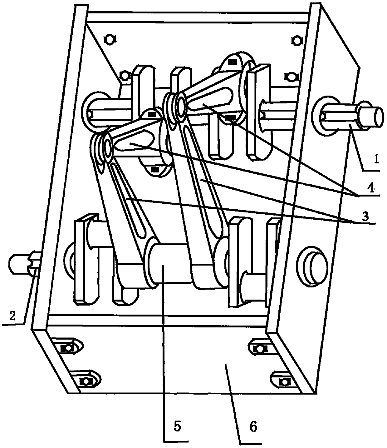
[0047] Such as figure 1 ,Such as Figure 3-10 Shown, a kind of mechanical power transmission device of crankshaft flywheel lever connecting rod structure, comprises crankshaft 1 (1), crankshaft 2 (2), flywheel lever (3), connecting rod (4), crankcase (6);

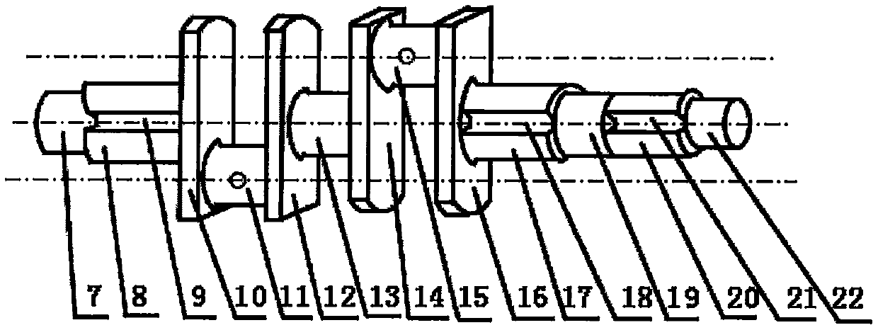
[0048]One end of the crankshaft 1 (1) is provided with the front end shaft 1 (7), one end of the front end shaft 1 (7) is provided with the main journal 1 (8), and the front end shaft 1 (7) is connected to the The main journal 1 (8) is cast into one body, the main journal 1 (8) is provided with the square groove 1 (9), the other end of the main journal 1 (8) and the crank arm 1 (10) The center position is shrink-fit connection, the other end of the crank arm 1 (10) is provided with the connecting rod journal 1 (11), and the other end of the connecting rod journal 1 (11) is provided with the crank arm 2 ( 12), the crankshaft arm 1 (10) and the connecting rod journal 1 (11) are integrally cast, and the connecting rod journa...

Embodiment 2

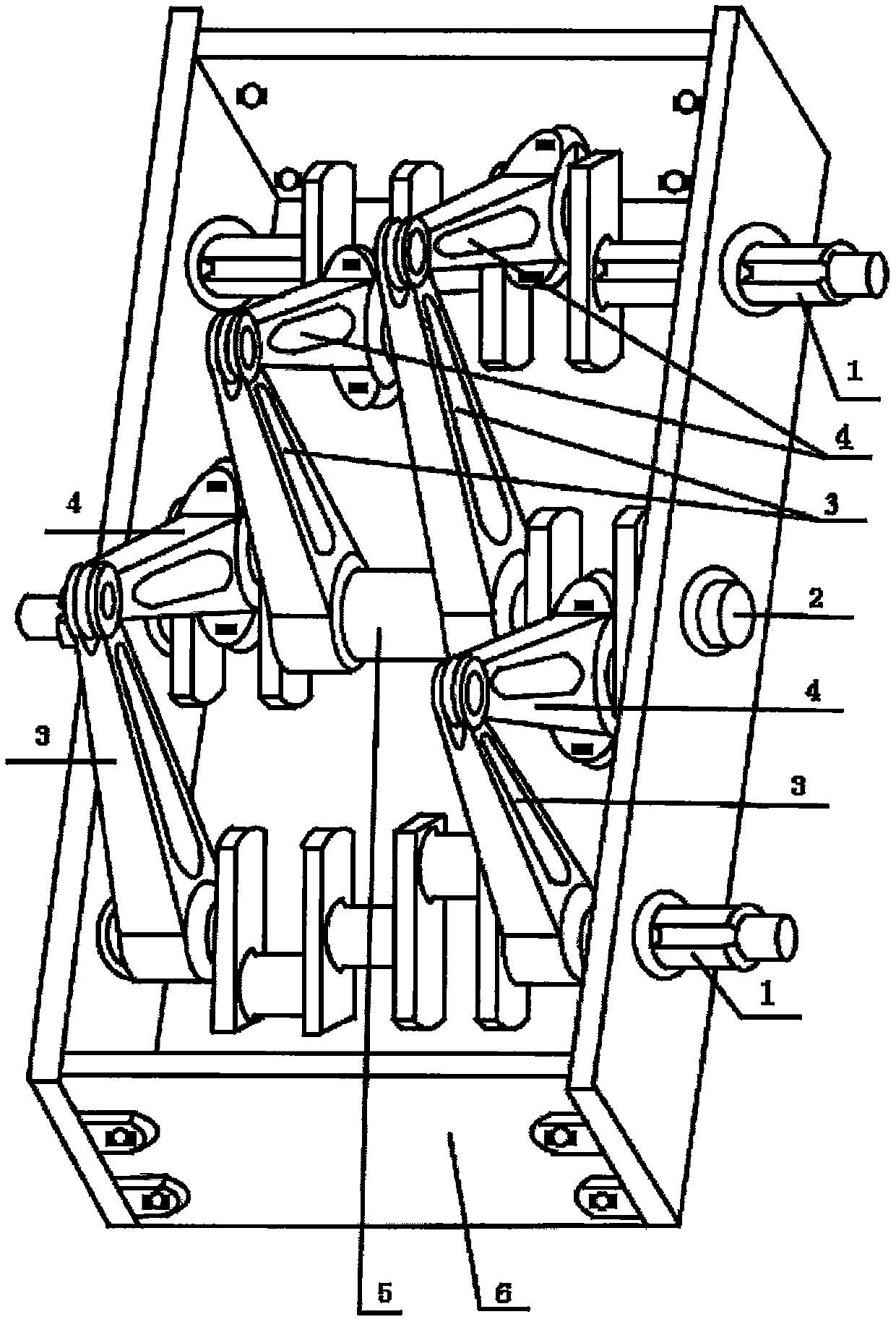
[0062] Such as figure 2 --shown in 10, the difference between this embodiment and embodiment 1 is: on the basis of embodiment 1, a described crankshaft 1 (1), described flywheel lever (3), described connecting rod (4) are added ) combination structure, has formed described crankshaft 1 (1), described crankshaft 2 (2), described flywheel lever (3), described connecting rod (4) two groups of crankshaft combination structures.

[0063] The front end shaft 1 (7) is connected to the upper bearing, the rear end shaft 1 (19) is connected to the upper bearing and is rotatably connected to the bearing hole (59), and the lever big head flywheel (42) is connected to the main journal 1 ( 8) Square groove card connection, the lever big head flywheel (42) is connected with the square groove card of the main journal 3 (17), the connecting rod big head (52) is connected to the upper connecting rod bearing bush, the connecting rod bearing cover (47) Connect the lower connecting rod bearing b...


PUM


Abstract

The invention discloses a mechanical power transmission device of a crankshaft, flywheel lever and connecting rod structure and belongs to the field of mechanical power. The mechanical power transmission device comprises a crankshaft 1, a crankshaft 2, a flywheel lever, a connecting rod and a crankcase, the crankshaft 2 comprises a crankshaft body 2A, a crankshaft body 2B and a main shaft neck connecting sleeve, the crankshaft 1 and the crankshaft 2 are each provided with a main shaft neck and a connecting rod shaft neck, the crankcase is provided with crankshaft holes, the crankshaft 1 and the crankshaft 2 are rotationally connected the crankshaft holes, the flywheel lever is connected with the main shaft necks, the connecting rod is rotationally connected with the connecting rod shaft necks, and the main shaft neck connecting sleeve is connected with the crankshaft body 2A and the crankshaft body 2B. According to the principles of the mechanical power transmission device, rotating motion is converted into up-down motion through a crankshaft connecting rod, then the up-down motion is converted into rotation motion through the flywheel lever, the flywheel characteristics and the lever principle are fully utilized to combine a flywheel and a lever into the flywheel lever, and the effects of increasing force and increasing the speed are achieved. The mechanical power transmissiondevice can be widely applied to the fields of vehicles, ships, engines, power generators, machines, new energy vehicles and the like, energy resources can be further saved, and the mechanical power transmission device can service the society.

Description

technical field [0001] The invention relates to a device capable of connecting a crankshaft, a flywheel lever and a connecting rod through bearings in a crankcase to achieve mechanical power transmission by inputting mechanical power, which belongs to the field of mechanical power, especially capable of increasing mechanical power And the mechanical power transmission device of a kind of crankshaft flywheel lever connecting rod structure that improves speed. Background technique [0002] At present, the known traditional mechanical power transmission methods include: chains, gears, belts, worm gears, ratchets, crankshaft connecting rods, etc. The mechanical power transmission devices composed of them can increase the limited mechanical power and speed, but cannot Fully meet the mechanical power and speed required by the machine. Contents of the invention [0003] In order to overcome the shortcomings of the above problems and change the traditional mechanical power transm...

Claims


Application Information

Patent Timeline
Patent Type & Authority Applications(China)
IPC IPC(8): F16H21/18
CPCF16H21/18
Inventor 唐乾程
Owner 唐乾程
Learn More