
Rotor for a motor

A motor rotor and shaft technology, which is applied in the field of motor rotors, can solve the problems of vibration, shortening the service life of the motor, and unsmooth operation, so as to achieve the effects of reducing vibration, smooth operation, and improving operation efficiency

Inactive Publication Date: 2019-05-07
SUNONWEALTH ELECTRIC MACHINE IND
View PDF5 Cites 0 Cited by
  • Summary
  • Abstract
  • Description
  • Claims
  • Application Information

AI Technical Summary

Problems solved by technology

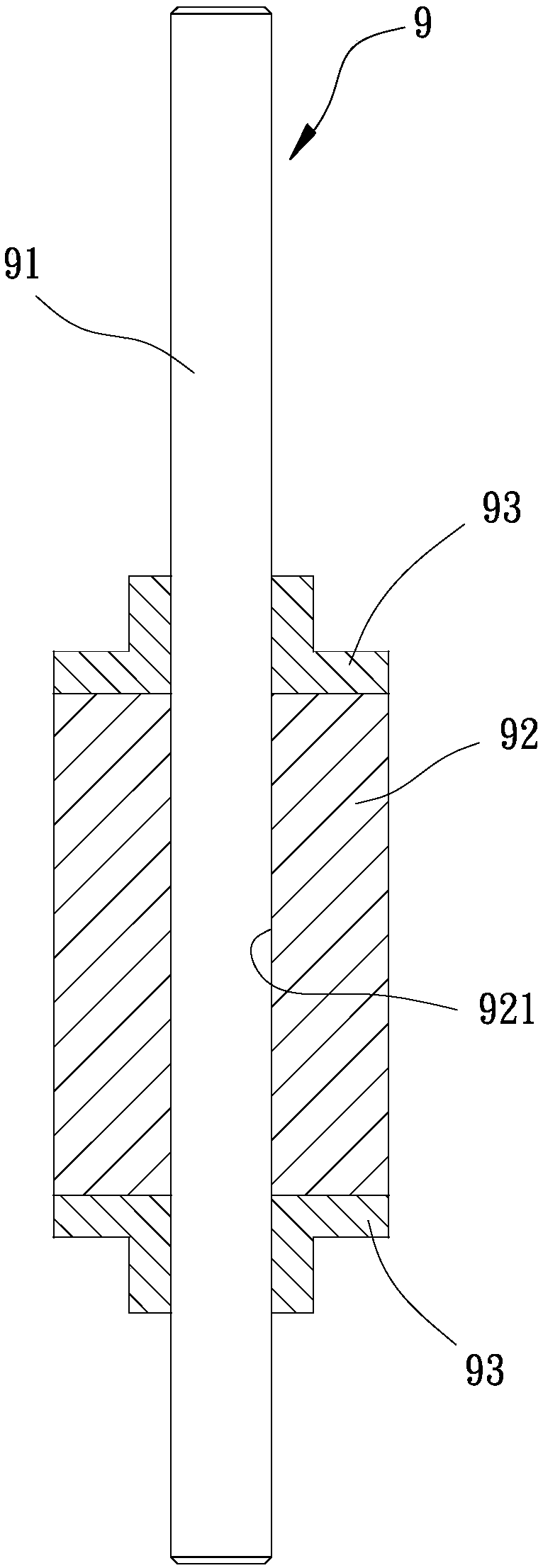
[0005] Although the above-mentioned existing motor rotor 9 can effectively avoid the fragmentation of the magnetic part 92, and can also securely fix the magnetic part 92 at a predetermined position on the rotating shaft 91; The magnetic part 92 will drive the rotating shaft 91 to rotate at a high speed and generate vibration, and then transmit the vibration to the two fixing seats 93, and then to the rotating shaft 91 closely connected with the two fixing seats 93, resulting in vibration generated when the whole motor is in operation. Vibration will not only produce operating noise, but also cause problems such as poor operation and shortened motor life.

Method used


Image

  • Rotor for a motor
  • Rotor for a motor
  • Rotor for a motor

Examples


no. 5 example

[0074] Please refer to Figure 8 , which is the fifth embodiment of the motor rotor of the present invention. The fifth embodiment of the present invention is substantially the same as the above-mentioned first embodiment. At least one first engaging portion 32 is provided, and at least one second engaging portion 45 is respectively provided on one of the axial end faces of the two assembly parts 4e, so that the two assembly parts 4e can be separated by the at least one The second engaging portion 45 is engaged with the corresponding first engaging portion 32, so as to improve the joint stability between the two assembly parts 4e and the permanent magnet 3, and at the same time help to quickly connect each assembly part 4e The plurality of positioning holes 42 on the upper part are opposite to the plurality of through holes 22 of the elastic collar 2, so as to lock the fixing component 5, so as to improve the convenience and efficiency of assembly.

[0075] Wherein, the first...


PUM


Abstract

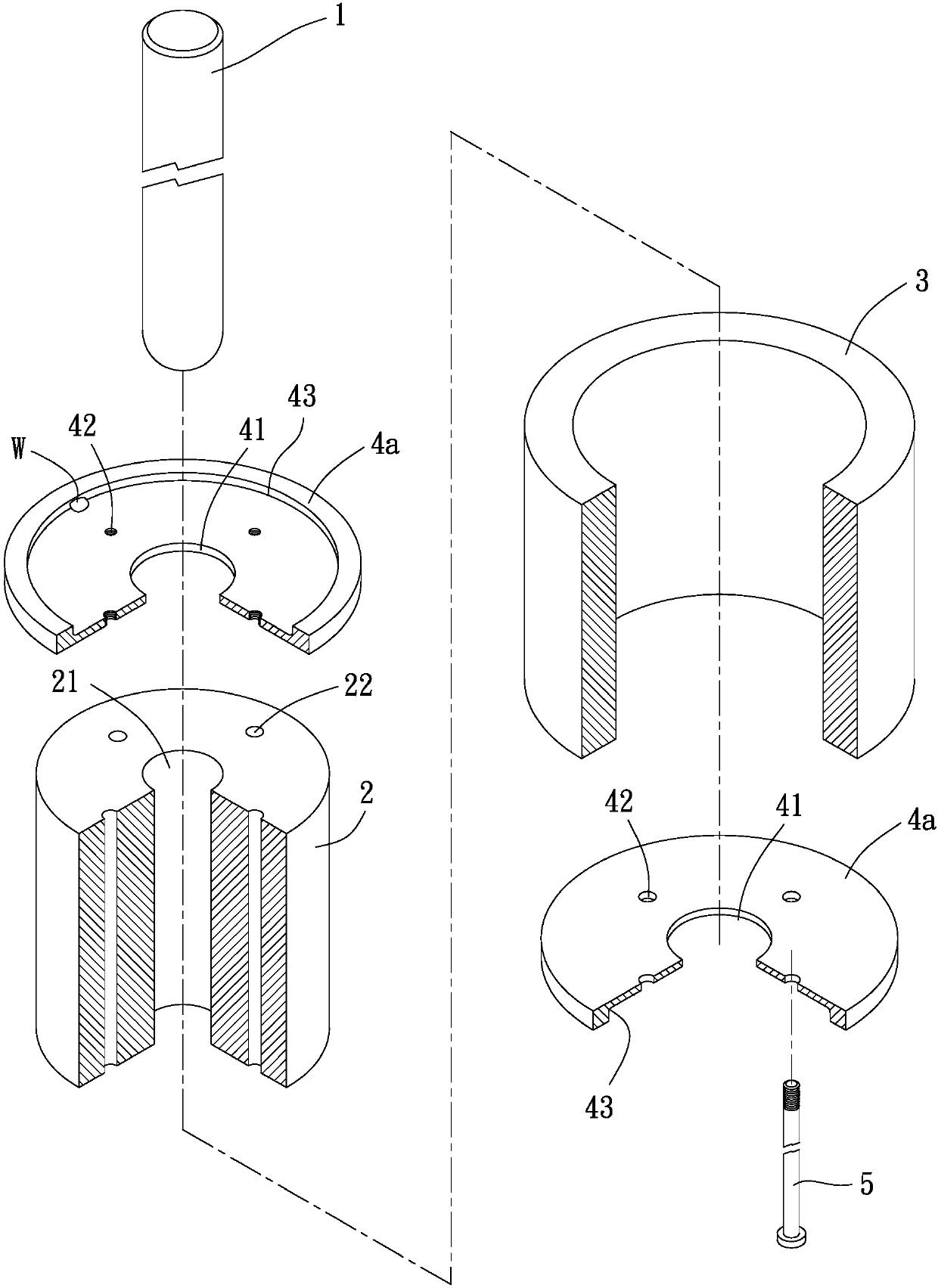
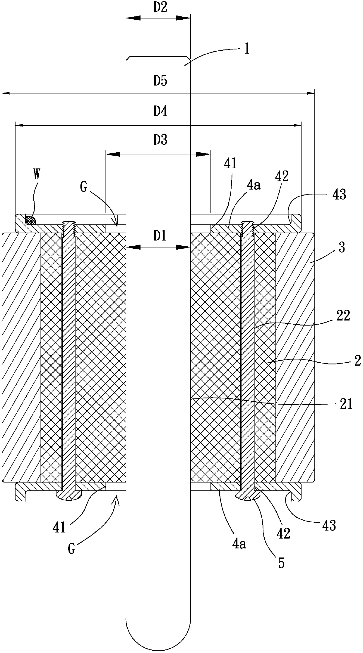
A rotor for a motor according to the invention is provided to solve the problem where the rotor of the conventional motor does not have an excellent vibration-reducing effect. The rotor for the motorincludes a shaft, an elastic sleeve, a permanent magnet and two engaging units. The elastic sleeve is fit around the shaft. The permanent magnet is fit around the elastic sleeve. The elastic sleeve and the permanent magnet have two sides spaced from each other in an axial direction. The two engaging units are coupled with the elastic sleeve and the permanent magnet at the two sides, respectively.Each of the two engaging units includes a through-hole through which the shaft extends. The two engaging units are not in contact with the shaft.

Description

technical field [0001] The present invention relates to a motor rotor, in particular to a motor rotor for an inner rotor motor. Background technique [0002] The motor rotor used in the early days of the inner rotor motor was directly coupled with the magnetic parts to the shaft, or the magnetic parts were clamped on the shaft through key blocks, so that the shaft and the magnetic parts could rotate synchronously. Embodiments similar to the aforementioned conventional motor rotors have been disclosed in Taiwan Publication No. I572125 and Patent No. 200744290. [0003] However, the tight fit combination of the magnetic part and the rotating shaft is likely to cause the fragmentation of the magnetic part; and the combination of the key block is difficult to ensure the stable combination of the magnetic part and the rotating shaft, so the existing motor rotor often causes the motor to run incorrectly. smooth, resulting in problems such as poor operating efficiency and noise. ...

Claims


Application Information

Patent Timeline
Patent Type & Authority Applications(China)
IPC IPC(8): H02K1/22H02K1/27
CPCH02K1/2733H02K21/14H02K1/28H02K1/2713H02K15/03
Inventor 洪银树吴智铭萧嘉玮
Owner SUNONWEALTH ELECTRIC MACHINE IND
Learn More