
Beneficiation spiral chute

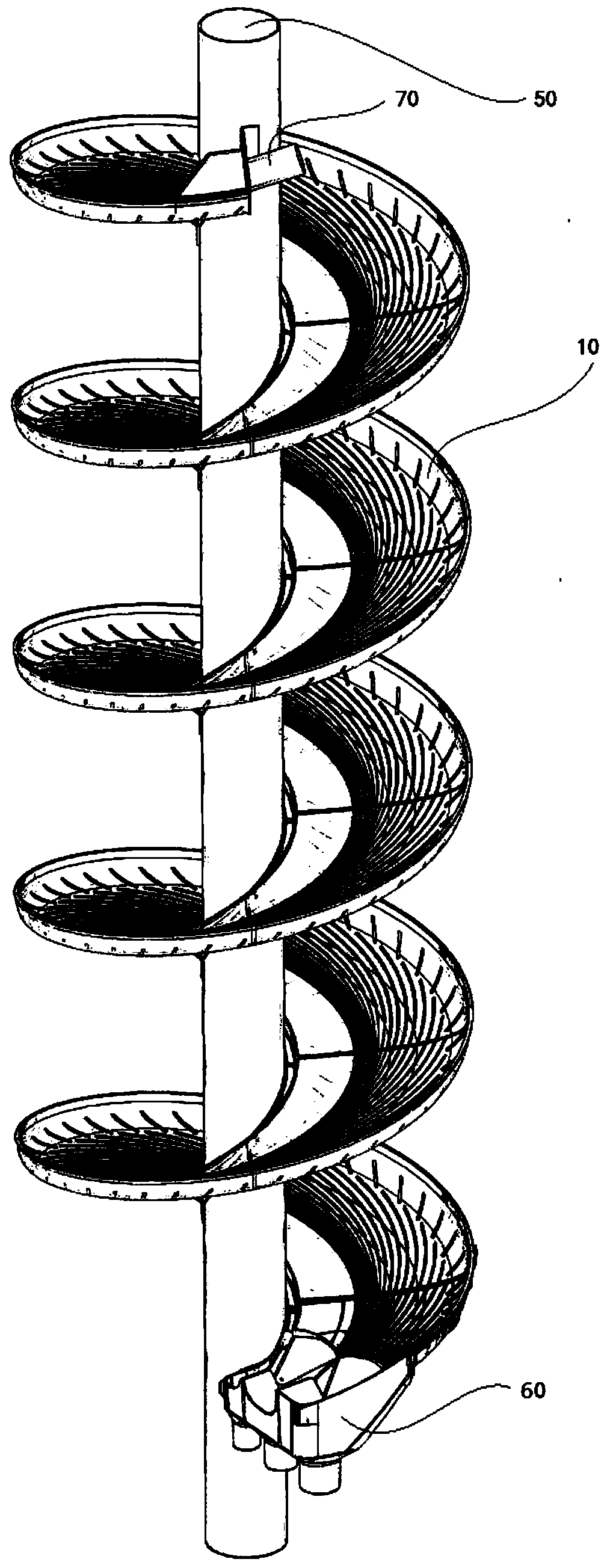
A technology of spiral chute and chute body, which is applied in the field of spiral chute for ore dressing, and can solve problems such as increasing energy consumption costs, increasing the proportion of heavy ore, and increasing the number of re-selection of medium ore

Pending Publication Date: 2019-05-10
李春鸥
View PDF11 Cites 9 Cited by
  • Summary
  • Abstract
  • Description
  • Claims
  • Application Information

AI Technical Summary

Problems solved by technology

However, the use of external mechanical force increases the centrifugal force of the spiral chute, and throws the "high sand dune wall" to the outside of the chute to improve the looseness of mineral particles, but at the same time, the heavy mineral particles inside the chute are displaced to the outside of the chute by the same centrifugal force. , resulting in an increase in the proportion of heavy ore in the intermediate mixed ore belt (ie, middle ore) between the heavy ore enrichment belt and the light ore tailings belt, thereby increasing the number of re-selection of the middle ore and increasing the cost of energy consumption

Method used


Image

  • Beneficiation spiral chute
  • Beneficiation spiral chute
  • Beneficiation spiral chute

Examples


Embodiment Construction

[0024] In order to facilitate the understanding of the present invention, the present invention will be described more fully below with reference to the associated drawings. Preferred embodiments of the invention are shown in the accompanying drawings. However, the present invention can be embodied in many different forms and is not limited to the embodiments described herein. On the contrary, the purpose of providing these embodiments is to make the disclosure of the present invention more thorough and comprehensive.

[0025] It should be noted that when an element is referred to as being “fixed” to another element, it can be directly on the other element or there can also be an intervening element. When an element is referred to as being "connected to" another element, it can be directly connected to the other element or intervening elements may also be present. In contrast, when an element is referred to as being "directly on" another element, there are no intervening ele...


PUM


Abstract

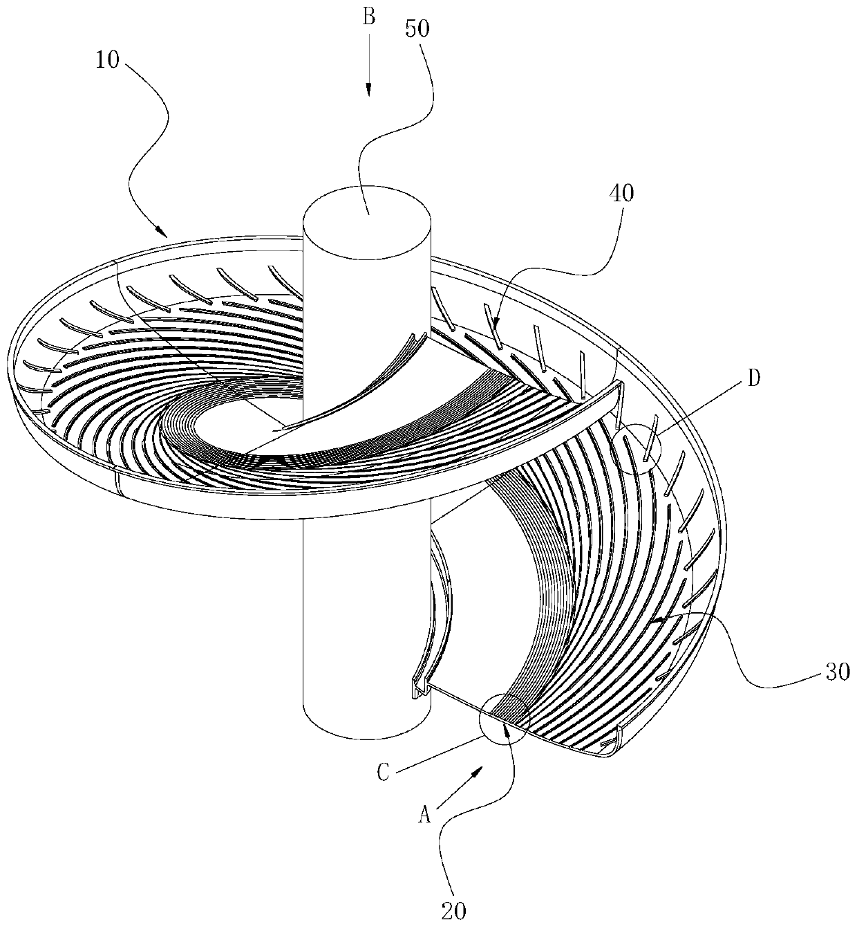
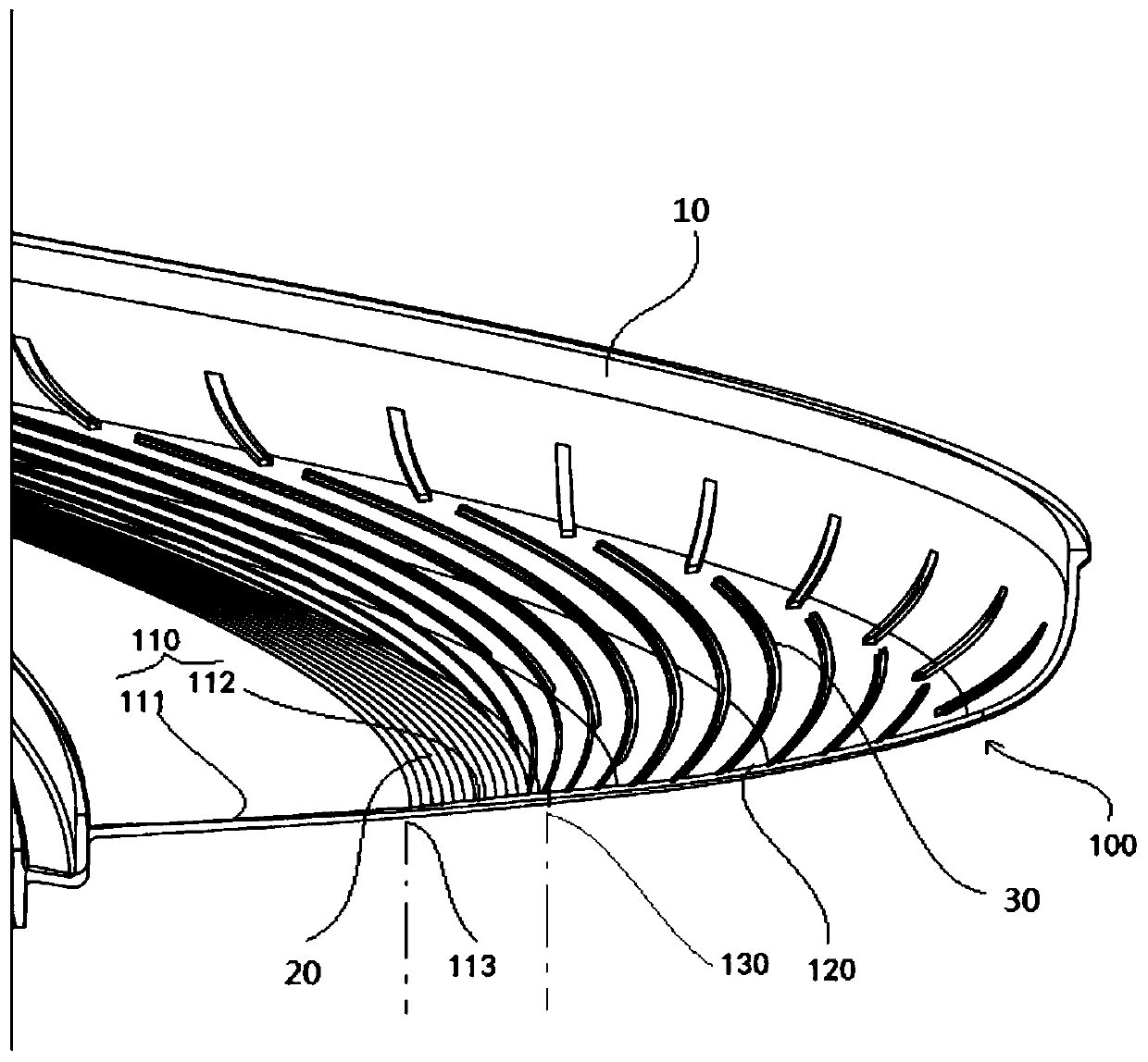
The invention relates to a beneficiation spiral chute which comprises a spiral chute body supported to be vertical. A radial transverse section curve of the chute body gradually rises from the inner side of the chute body to the outer side of the chute body. The radial transverse section curve of the chute body is a compound curve. The compound curve comprises a first curve section and a second curve section which are successively arranged from the inner side of the chute body to the outer side of the chute body. The tail end of the first curve section and the head end of the second curve section are connected to a first connecting point. The included angle between a curve tangent line of the head end of the second curve section and the horizontal plane is smaller than that between the curve tangent line of the tail end of the first curve section and the horizontal plane. The beneficiation spiral chute not only can unfold and thin a dune high wall outward to improve the looseness of mineral particles, but also can increase the throughput per hour, so that the beneficiation efficiency and effect are better.

Description

technical field [0001] The invention relates to the technical field of gravity beneficiation equipment, in particular to a beneficiation spiral chute. Background technique [0002] The mineral dressing spiral chute is a kind of mineral processing equipment based on the difference in density and specific gravity of mineral particles and the looseness of the film flow of mineral particles, so that minerals are physically separated under the action of centrifugal force and gravity compound force field. The shape of the beneficiation spiral chute directly determines the beneficiation effect. In the process of mineral separation in the traditional beneficiation spiral chute, when the pulp concentration increases to a certain level, coarser mineral particles often accumulate in the radial middle of the trough to form a "high wall of sand dunes" along the direction of the spiral tangent. The phenomenon of movement. This will lead to poor looseness among mineral particles, and blo...

Claims


Application Information

Patent Timeline
IPC IPC(8): B03B5/62
CPCB03B5/626B03B5/52B03B7/00
Inventor 李春鸥
Owner 李春鸥
Learn More