
Rolling mill manipulator lining plate

A lining plate and rolling mill technology, applied in the field of rolling mill pusher lining plate, can solve the problems of easy wear of cutting lining plates, large impact load, loose bolts, etc., and achieve the effects of preventing loosening, enhancing wear resistance and reasonable design.

Inactive Publication Date: 2019-05-10
FUHUA ZHONGYUAN JIANGSU HEAVY MACHINERY TECH CO LTD
View PDF3 Cites 0 Cited by
  • Summary
  • Abstract
  • Description
  • Claims
  • Application Information

AI Technical Summary

Problems solved by technology

[0002] The existing rolling mill pusher generally includes panels arranged relatively on both sides of the working roller table of the rolling mill. Lining plates are connected to the panels. When rolling steel, due to the large impact load of the rolling workpiece against the lining plate, it is easy to cause the bolts to loosen, resulting in lining The plate is loose, and the cutting liner is easy to wear

Method used


Image

  • Rolling mill manipulator lining plate

Examples


Embodiment Construction

[0009] The present invention is described in further detail now in conjunction with accompanying drawing. These drawings are all simplified schematic diagrams, which only illustrate the basic structure of the present invention in a schematic manner, so they only show the configurations related to the present invention.

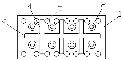
[0010] Such as figure 1 As shown, a rolling mill pusher liner includes a liner body 1, a number of bolt holes 2 are provided on the liner body 1, counterbores are provided on the surface of the bolt hole 2, and the horizontal direction of the liner body 1 is At least one first shock absorbing groove 3 is provided, and several second shock absorbing grooves 4 are longitudinally arranged on the liner body. The surface of the liner body 1 is also provided with several shock absorbing blind holes 5. The second shock absorbing groove 3 The number is 3, and the surface of the liner body 1 is also provided with ceramic wear-resistant particles.

[0011] Shock absor...


PUM


Abstract

The invention discloses a rolling mill manipulator lining plate. The lining plate comprises a lining plate body, the lining plate body is provided with a plurality of bolt holes, counter bores are formed in the surfaces of the bolt holes, at least one first damping groove is transversely formed in the lining plate body, a plurality of second damping grooves are longitudinally formed in the liningplate body, and a plurality of damping blind holes are formed in the surface of the lining plate body. According to the rolling mill manipulator lining plate, damping grooves are used for damping, sothat the lining plate is prevented from loosening; the contact area between the lining plate and a panel is reduced through the damping grooves and the damping blind holes, so that the wear-resistanteffect is achieved; and the wear-resistant effect of the lining plate is further enhanced through ceramic wear-resistant particles. The rolling mill manipulator lining plate is reasonable in design and suitable for popularization and application.

Description

technical field [0001] The invention relates to a pusher liner for a rolling mill. Background technique [0002] The existing rolling mill pusher generally includes panels arranged relatively on both sides of the working roller table of the rolling mill. Lining plates are connected to the panels. When rolling steel, due to the large impact load of the rolling piece against the lining plate, it is easy to cause the bolts to loosen and cause the lining plate to loosen. The board is loose, and the cutting liner is easy to wear. Contents of the invention [0003] In order to overcome the above disadvantages, the present invention provides a rolling mill pusher liner, including a liner body, a number of bolt holes are arranged on the liner body, counterbores are provided on the surface of the bolt holes, and the liner body There is at least one first shock absorbing groove arranged horizontally on the upper side, and several second shock absorbing grooves are arranged longitud...

Claims


Application Information

Patent Timeline
Patent Type & Authority Applications(China)
IPC IPC(8): B21B39/14
Inventor 李文刚
Owner FUHUA ZHONGYUAN JIANGSU HEAVY MACHINERY TECH CO LTD
Learn More