
Holemaking tool with independent drill point in the center

A hole processing and drilling technology, applied in the field of hole processing tools, can solve the problems of small cutting load, poor centering ability, and reduce the stability of the cutting workpiece, so as to ensure dimensional accuracy and surface quality, avoid excessive cutting temperature, The effect of excellent collapse resistance

Active Publication Date: 2021-06-04
ZHUZHOU CEMENTED CARBIDE CUTTING TOOLS CO LTD
View PDF0 Cites 0 Cited by
  • Summary
  • Abstract
  • Description
  • Claims
  • Application Information

AI Technical Summary

Problems solved by technology

The drill point with a small apex angle has strong centering ability when drilling, but the cutting force is large and the strength is poor. The centering ability of the drill point with a large apex angle is poor when drilling, but the cutting load is small.
In order to reduce the cutting force and improve the efficiency of the tool, the drill tip angle of the drilling tool is generally 120° to 140°, but such a large drill tip angle will cause the cutting process of the drilling tool to be too fast, and the chips will be excessively squeezed on the cutting edge. The pressure reduces the stability when cutting into the workpiece, especially when drilling on an inclined surface. In order to improve the processing accuracy, pre-drilling is generally required, and the processing efficiency is low.

Method used


Image

  • Holemaking tool with independent drill point in the center
  • Holemaking tool with independent drill point in the center
  • Holemaking tool with independent drill point in the center

Examples


Embodiment 1

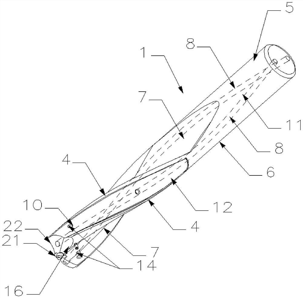
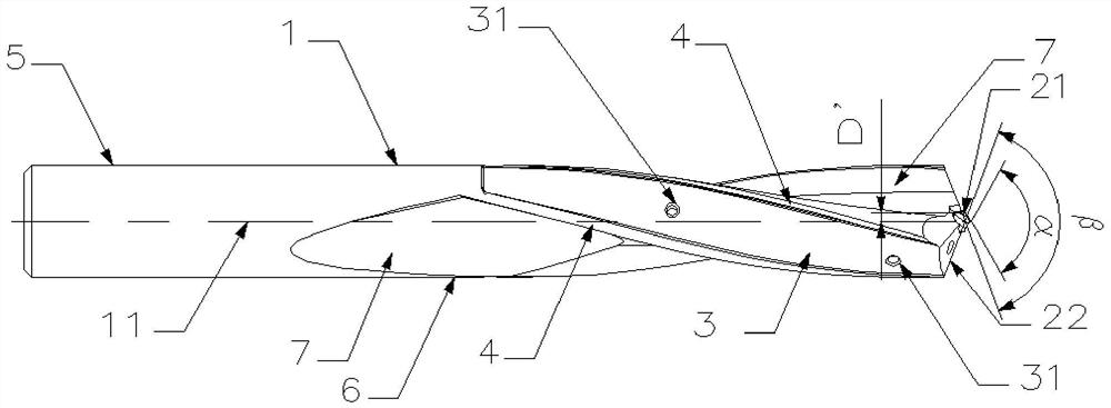
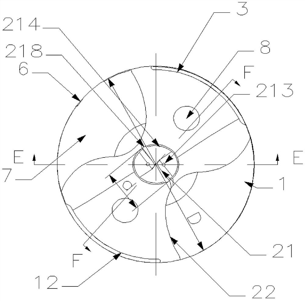
[0032] Such as Figure 1 to Figure 5 As shown, the center of this embodiment has a hole processing tool with an independent drill tip, including a cutter body 1 and a drill tip 2, and the drill tip 2 includes an inner drill tip 21 and an outer drill tip 22, and the outer drill tip 22 is arranged on the cutter body 1 , the inner drill tip 21 is installed in the center of the outer drill tip 22 and forms the core of the outer drill tip 22, the inner drill tip 21 partially protrudes from the outer drill tip 22, and the cutting depth of the inner drill tip 21 is greater than the cutting depth of the outer drill tip 22 .

[0033] The drill tip 2 is composed of an inner drill tip 21 and an outer drill tip 22. The inner drill tip 21 and the outer drill tip 22 cut into the workpiece layer by layer in the direction of cutting depth. The inner drill tip 21 cuts into the workpiece first and then the outer drill tip 22 cuts into the workpiece , which prolongs the time for the drill tip 2...

Embodiment 2

[0042] Such as Figure 6 to Figure 9 As shown, the hole machining cutter of the present embodiment differs from Embodiment 1 in that:

[0043] The cutter body 1 and the outer drill tip 22 are made of the same material and are integral non-removable structures. The inner drill tip 21 is fixedly connected with the outer drill tip 22 by welding, and the drill tip 2 and the cutter body 1 form a fixed integral structure, so that there is no Additional fastening screws 15 are required.

[0044] In this embodiment, the cross section of the inner clearance surface 214 and the side wall surface of the countersink hole 224 are circular, and one side of the inner clearance surface 214 is tangent to the wall surface of the countersunk hole 224, and the other side is tangent to the wall surface of the countersink hole 224. The wall surfaces of 224 are clearance fit, and the maximum clearance of clearance fit is Y, which should satisfy 0.05mm≤Y≤0.3mm. There is an offset distance Z between...


PUM


Abstract

The invention discloses a hole processing tool with an independent drill point in the center, which includes a cutter body and a drill point. The drill point includes an inner drill point and an outer drill point which are independent of each other. The center of the drill tip forms the core of the outer drill tip, and the depth of cut of the inner drill tip is greater than that of the outer drill tip. The drill tip of the present invention is composed of an inner drill tip and an outer drill tip. The inner and outer drill tips cut into the workpiece layer by layer in the cutting depth direction. After the inner drill tip cuts into the workpiece and stabilizes, the outer drill tip cuts into the workpiece again, prolonging the time for the drill tip to cut into the workpiece. Greatly improve the stability of the drill tip drilling into the workpiece; because the inner drill tip is independent of the outer drill tip, the inner drill tip can have a small drill tip angle and the outer drill tip can have a large drill tip angle, and the inner drill tip can have a small drill tip angle. The apex angle of the drill point can prevent the cutting process of the tool from being too fast, and the chips will be excessively squeezed on the cutting edge, which improves the stability when cutting into the workpiece; the inner drill point can be interchanged in batches, and can be flexibly combined and installed on the outer drill point, which greatly reduces the cutting time of the hole drilling tool. inventory.

Description

technical field [0001] The invention relates to a metal cutting tool, in particular to a hole processing tool with an independent drill point in the center. Background technique [0002] When the drilling tool is cutting, the cutting end is mainly subjected to the cutting force, and the chips can only be discharged from the cutting end through the chip groove. Since the cutting speed of the drilling tool varies greatly, and the center cutting speed is zero, the drilling During processing, especially during drilling into the workpiece, most of the axial cutting force is borne by the central cutting edge of the drilling tool. Drill points with small apex angles have strong centering ability but high cutting force and poor strength when drilling. Drill points with large apex angles have poor centering ability but small cutting load when drilling. In order to ensure drilling accuracy and cutting efficiency. In order to reduce the cutting force and improve the efficiency of the ...

Claims


Application Information

Patent Timeline
Patent Type & Authority Patents(China)
IPC IPC(8): B23B51/00B23B51/06
Inventor 王社权江爱胜刘敏赵志伟吴火飞项兴东
Owner ZHUZHOU CEMENTED CARBIDE CUTTING TOOLS CO LTD
Learn More