
Rail press and rail

A technology of rail presser and fixed base, applied in the field of rails, can solve the problems of difficult installation, high construction intensity, rail displacement, etc., and achieve the effects of high resistance to lateral force, high maintenance difficulty, and low maintenance frequency.

Pending Publication Date: 2019-05-10
林州市宏阳工业设备有限公司
View PDF0 Cites 0 Cited by
  • Summary
  • Abstract
  • Description
  • Claims
  • Application Information

AI Technical Summary

Problems solved by technology

[0004] In the first method of track fixing, a large number of openings on the steel beam will weaken the strength of the load-bearing beam and the steel rail. At the same time, this method has high construction strength and difficult installation. After the pressure plate is installed, the steel load-bearing beam will vibrate after being affected by the operation of the vehicle. , causing the bolts fixing the pressure plate to loosen, and the pressure plate cannot press the track tightly, causing the track to shift
The second rail fixing method has the advantages of high rail installation accuracy, but also has disadvantages, that is, due to the external lateral force and vibration of the rail, the adjustment plate will fall off, causing the upper cover to not press the rail tightly, causing the rail to loosen
The third rail fixing method is easy to install and has the advantages of a certain locking function. However, when the rail is subjected to strong impact and lateral force, the upper cover will also shift, causing the rail to loosen.
Specifically, the junction between the T-bolt and the fixed base is a flat bottom, and the strength of the stress-bearing part of the flat-bottom structure is low. The impact force, vibration force and lateral force will easily deform the stress-bearing part of the T-bolt, resulting in a series of problems such as the upper cover not being pressed tightly on the track, the track shifting, and the gauge changing.

Method used


Image

  • Rail press and rail
  • Rail press and rail
  • Rail press and rail

Examples


Embodiment Construction

[0087] The technical solutions in the embodiments of the present application will be described below with reference to the drawings in the embodiments of the present application.

[0088] It should be noted that like numerals and letters denote similar items in the following figures, therefore, once an item is defined in one figure, it does not require further definition and explanation in subsequent figures. Meanwhile, in the description of the present application, the terms "first", "second" and the like are only used to distinguish descriptions, and cannot be understood as indicating or implying relative importance.

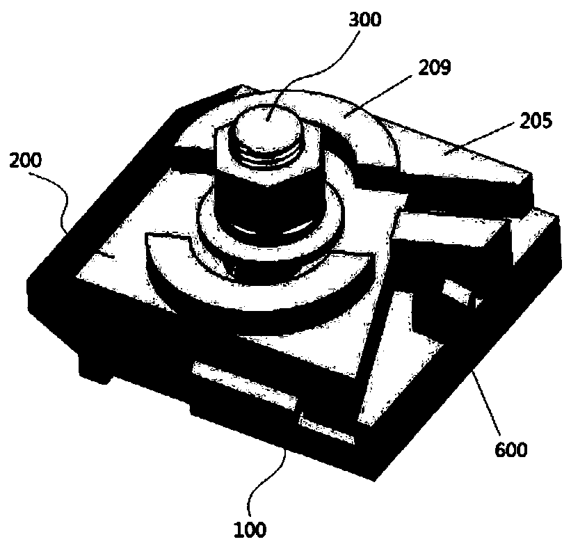
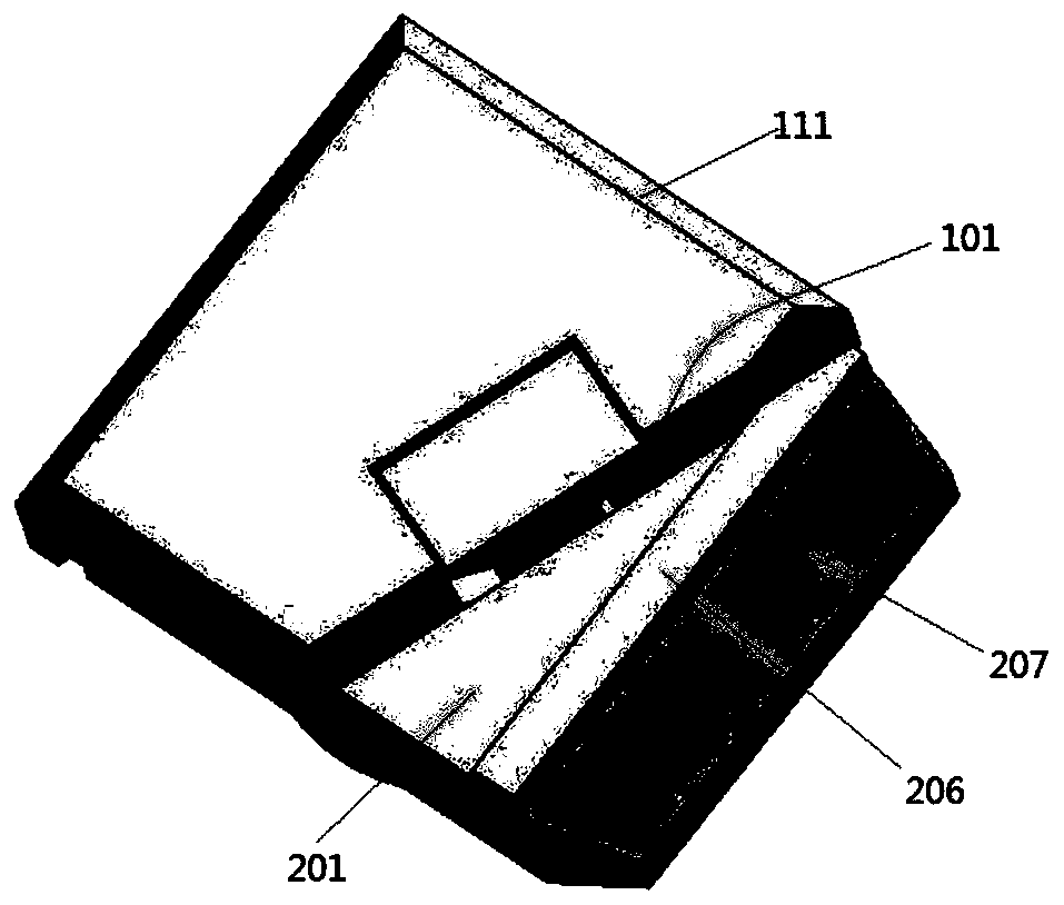
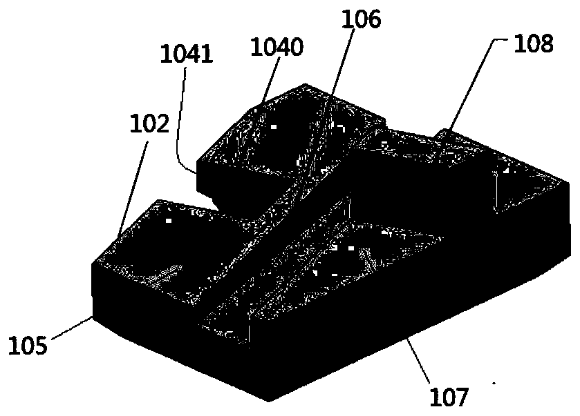
[0089] Please see figure 1 , figure 1 A schematic structural view of a rail clamp provided by one of the embodiments of the present application is shown. figure 2 show figure 1 Bottom view of the rail clamp shown. Such as figure 1 and figure 2 As shown, the rail clamp includes a fixed base 100 and an upper cover 200 , and the upper cover 200 covers the...


PUM


Abstract

The embodiment of the application provides a rail press and a rail. The rail press comprises a fixed base and an upper cover, the upper cover covers the fixed base, first locking member enabling the fixed base and the upper cover to achieve two-way anti-retreating self-locking in the sided direction and a bucket-shaped bolt member penetrating through the upper cover and the fixed base in the perpendicular direction and fixing the upper cover and the fixed base are configured between the fixed base and the upper cover, and a gradual contraction mounting hole matched with the bucket-shaped boltmember is formed in the fixed base. The rail press can solve the problems such as loosening, falling off, rail displacement and change of gauge of the rail press due to the huge lateral force passed to the rail in the operation process of lifting transport equipment, meanwhile, the problems of high difficulty of the user maintenance and the high maintenance cost are further solved, and the requirements of the rails such as various heavy-duty, large lifting transport equipment and coke oven four large vehicles are met.

Description

technical field [0001] The present application relates to the technical field of rail fixing, and in particular, to a rail clamp and a rail using the rail clamp. Background technique [0002] At present, with the advancement of science and technology and the rapid development of industrial modernization, high-speed railways, subways, and intercity railways are developing rapidly. The requirements for track installation accuracy and stability of equipment are getting higher and higher. Correspondingly, track fixing devices with high installation accuracy, good firmness, and long service life are required to improve track installation accuracy and track stability, and ensure lifting Smooth operation of transport equipment, rolling stock. [0003] In the field of track fixing, traditional track fixing methods are generally divided into three types: the first is the perforated steel beam type, that is, a large number of holes are opened on the flange plate of the steel beam, an...

Claims


Application Information

Patent Timeline
Patent Type & Authority Applications(China)
IPC IPC(8): B66C7/08E01B23/14
Inventor 纪付军
Owner 林州市宏阳工业设备有限公司
Learn More