
Steam turbine multi-stage steam cylinder combined cooling system

A combined cooling and steam turbine technology, applied in mechanical equipment, engine components, machines/engines, etc., can solve the problems of life damage of cylinder 2 and rotor 1, loss of flow capacity, cold shock, etc., to save energy, avoid losses, The effect of avoiding life damage

Pending Publication Date: 2019-05-10
SHANGHAI ELECTRIC POWER GENERATION EQUIPMENT CO LTD
View PDF0 Cites 0 Cited by
  • Summary
  • Abstract
  • Description
  • Claims
  • Application Information

AI Technical Summary

Problems solved by technology

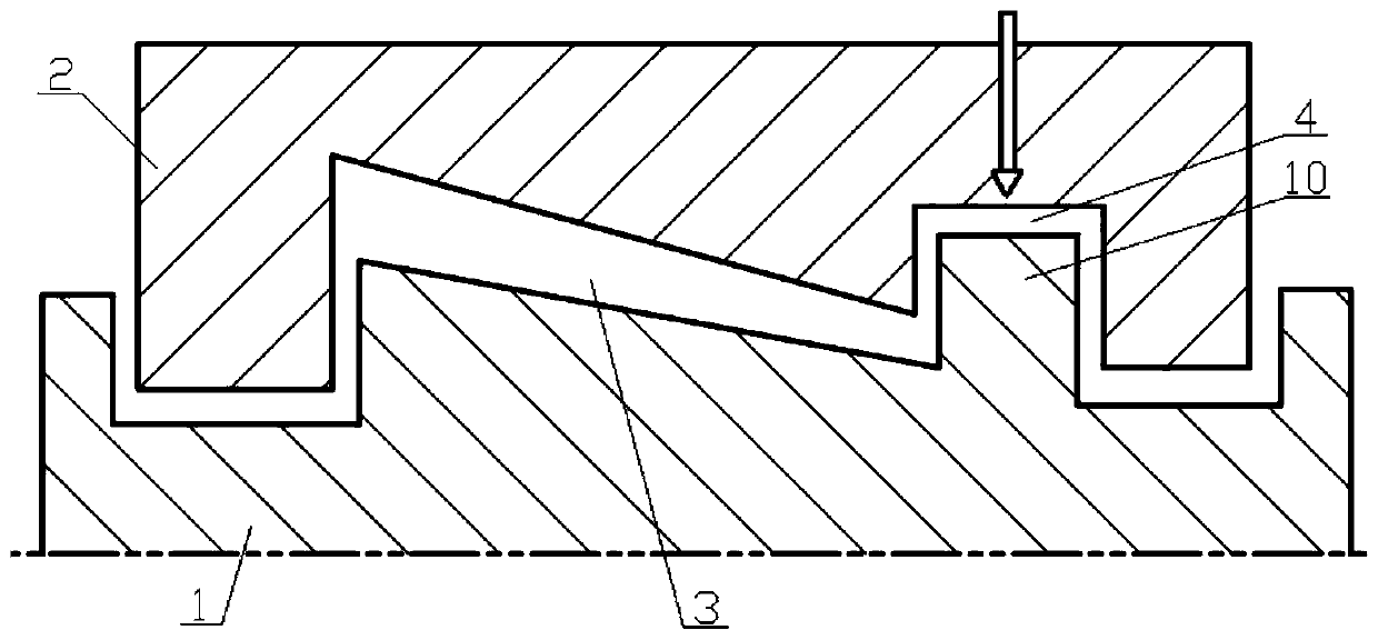
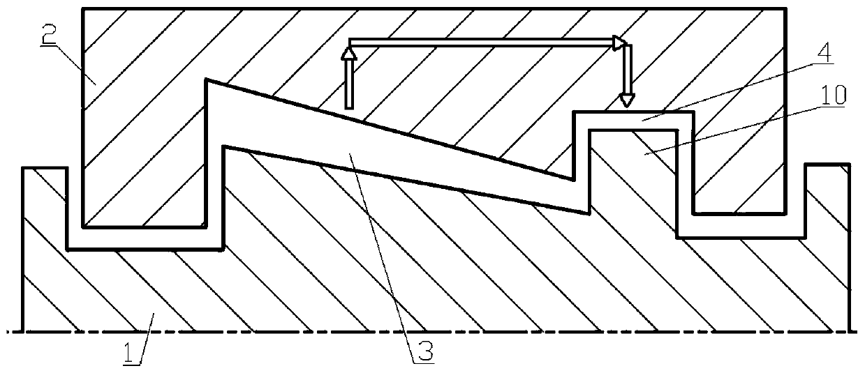
[0004] The above-mentioned cooling method has the following defects: extracting steam from the exhaust steam of the front cylinder as cooling steam is easy to form a cold shock in the area to be cooled 4, causing life damage to the cylinder 2 and rotor 1
Extraction of steam from the flow area 3 in the own cylinder 2 as cooling steam results in a loss of the flow capacity of the own cylinder 2

Method used


Image

  • Steam turbine multi-stage steam cylinder combined cooling system
  • Steam turbine multi-stage steam cylinder combined cooling system
  • Steam turbine multi-stage steam cylinder combined cooling system

Examples


Embodiment Construction

[0030] The specific implementation manners of the present invention will be described in further detail below in conjunction with the accompanying drawings. These embodiments are only used to illustrate the present invention, not to limit the present invention.

[0031] In the description of the present invention, it should be noted that the terms "center", "longitudinal", "transverse", "upper", "lower", "front", "rear", "left", "right", " The orientations or positional relationships indicated by "vertical", "horizontal", "top", "bottom", "inner", "outer", etc. are based on the orientation or positional relationships shown in the drawings, and are only for the convenience of describing the present invention and simplifying Describes, but does not indicate or imply that the device or element referred to must have a specific orientation, be constructed in a specific orientation, and operate in a specific orientation, and therefore should not be construed as limiting the inventio...


PUM


Abstract

The invention relates to the technical field of steam turbine cooling, in particular to a steam turbine multi-stage steam cylinder combined cooling system. The steam turbine multi-stage steam cylindercombined cooling system comprises a front rotor, a front steam cylinder, a rear rotor and a rear steam cylinder. The front steam cylinder sleeves the front rotor, a first to-be-cooled region is formed between the front steam cylinder and the front rotor, and the front steam cylinder comprises a hole channel which guides cooling steam into the first to-be-cooled region. The rear steam cylinder sleeves the rear rotor, a second to-be-cooled region is formed between the rear steam cylinder and the rear rotor and communicates with the first to-be-cooled region through a pipeline, and the waste steam in the first to-be-cooled region is guided by the pipeline into the second to-be-cooled region. The waste steam which is generated after the cooling cycle of the cooling steam of the front steam cylinder is accomplished is recycled, and serves as the cooling steam to be used for cooling the second to-be-cooled region of the rear steam cylinder, the mode is an effective mode of waste steam energy cascading utilization, the loss of the flow circulation capacity of the rear steam cylinder can be avoided, and the phenomenon that the cold shock causes the lift damage to the rear steam cylinder and the rear rotor is avoided.

Description

technical field [0001] The invention relates to the technical field of steam turbine cooling, in particular to a combined cooling system between multi-stage cylinders of a steam turbine. Background technique [0002] Cooling technology is widely used in the design of steam turbine cylinder and rotor in high temperature and high pressure steam environment. Taking the single-stream arrangement as an example, such as figure 1 with figure 2 As shown, in order to balance the axial thrust of the flow stage, a balance piston 10 with a relatively high diameter is designed on the rotor 1. The balance piston 10 is located on one side of the flow area 3 in the cylinder 1, and the rotor disc in the area where the balance piston 10 is located is affected by The high temperature of the incoming steam and the harsh environment of the centrifugal force of the rotor usually need to be cooled by a cooling system, that is, a region 4 to be cooled is formed between the balance piston 10 and ...

Claims


Application Information

Patent Timeline
IPC IPC(8): F01D25/12
Inventor 顾永丹王海涛华文祥仪剑
Owner SHANGHAI ELECTRIC POWER GENERATION EQUIPMENT CO LTD
Learn More