Pin type insulator

A pin-type insulator, insulating pin technology, applied in the direction of pin-type insulators, insulators, electrical components, etc., can solve the problems of disconnection, wear of contact parts, wire falling off, etc., achieve good economic and social benefits, and reduce breakdown. possible, the effect of preventing loosening and falling off

Inactive Publication Date: 2019-05-10
江西省萍乡市宇翔电瓷制造有限公司
View PDF0 Cites 3 Cited by
  • Summary
  • Abstract
  • Description
  • Claims
  • Application Information

AI Technical Summary

Problems solved by technology

The main fixing method of the wires fixed by pin insulators is generally the binding wire winding method. The binding wire winding method is not only complicated in binding, but also has low installation efficiency. There are also some problems in the structure: aluminum stranded wire and steel core aluminum stranded wire The wire materials are the same, and the wires are affected by weather conditions such as wind, ice, and low temperature all the year round, and strong vibrations often occur, causing the contact parts to wear out, and then disconnection occurs; Aging and falling off under the wind and sun, loosening makes the fixation unstable, the exposed iron wire cuts the outer layer of the wire insulation and breaks the outer insulation, and further cuts the wire. If the wire falls off, it will cause single-phase grounding, and in severe cases, it will cause a short circuit between phases, which will increase the occurrence rate and maintenance rate of electric accidents, and reduce the stability and reliability of the line.

Method used


Image

  • Pin type insulator
  • Pin type insulator
  • Pin type insulator

Examples


Embodiment Construction

[0027] The following will clearly and completely describe the technical solutions in the embodiments of the present invention with reference to the accompanying drawings in the embodiments of the present invention. Obviously, the described embodiments are only some, not all, embodiments of the present invention. All other embodiments obtained by persons of ordinary skill in the art based on the embodiments of the present invention belong to the protection scope of the present invention.

[0028] According to an embodiment of the present invention, a pin insulator is provided.

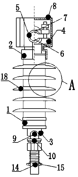
[0029] Such as Figure 1-3 As shown, the pin insulator according to the embodiment of the present invention includes an insulating pin body 1, and the insulating pin body 1 includes a connecting end portion 2 and a fitting end portion 3, and the fitting end portion 3 is located at the end of the connecting end portion 2. below, among them;

[0030] The top end of the connection end 2 is provided with ...


PUM


Abstract

The invention discloses a pin type insulator. The pin type insulator comprises an insulating pin body; the insulating pin body comprises a connecting end part and a fitting end part; the fitting end part is located below the connecting end part; a clamping seat is arranged at the top end of the connecting end part; a wire clamping groove is formed in the clamping seat; a puncture electrode and a puncture tooth pressing block are arranged in the wire clamping groove; the puncture tooth pressing block is located above the puncture electrode; an insulating cover is arranged outside the clamping seat; a steel leg is connected to the bottom end of the fitting end part; a spring washer and a locking nut are arranged on the steel leg in a sleeving mode; one side of the locking nut is connected with a spring; a through hole is formed in one side, located at the spring, of the steel leg; and a limiting clamp is inserted in the through hole. The pin type insulator is reasonable in structure, safe and reliable in performance and easy to install and use, and has relatively high economic and social benefits.

Description

technical field [0001] The invention relates to the technical field of power transmission accessories, in particular to a pin insulator. Background technique [0002] Power needle insulators are widely used in power systems. Overhead transmission lines, busbars of power plants and substations, and external live conductors of various electrical equipment must be supported by insulators and connected to the earth (or ground) or Other conductors with potential difference are insulated. [0003] As for the pin insulators currently used in overhead power distribution lines, the traditional pin insulators are composed of porcelain parts and iron feet extending into the porcelain parts. The iron feet are installed inside the porcelain parts and then glued with cement. Withstand bending load and have good bending resistance. The main fixing method of the wires fixed by pin insulators is generally the binding wire winding method. The binding wire winding method is not only complica...

Claims


Application Information

Patent Timeline
Patent Type & Authority Applications(China)
IPC IPC(8): H01B17/22H01B17/42
Inventor 苏欢
Owner 江西省萍乡市宇翔电瓷制造有限公司
Why Eureka
Try Eureka